Back to Sidestreet Bannerworks
Click here to find out how your engine can be featured!
.


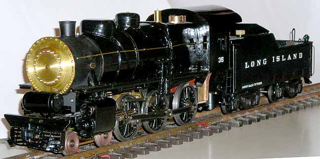
Long Island Railroad G5 No. 35
by Ernie Noa
Monticello, Illinois
Photos by the author
November, 2011
Locomotive No. 35 was built in 1928 by the Pennsylvania Railroad's Juniata Shops to transport commuters on the Long Island Railroad (LIRR). It was part of the last of three batches, which replaced the earlier 4-4-0s, as these were unable to pull the heavyweight steel coaches of the era.
No. 35 has 68" driving wheels and a working pressure of 205 pounds. The relatively small drivers let the locomotive accelerate quickly between the closely spaced stations found in commuter service on Long Island.
The locomotive had a weight of 237,000 lbs. (118.5 tons) and a rated top speed 75 mph, but probably ran faster on occasion. It was hand fired, with a tender capacity of 14-1/2 tons of coal and 12,730 gallons of water
The G5s remained in commuter service and occasional light freight duty until being retired in the mid 1950s. No. 35 was one of the last steam locomotives in service on the LIRR and even participated in the end-of-steam ceremony, as well as being the last LIRR steam engine to haul an excursion in October of 1995.
No. 35 is one of three PRR-built G5s preserved, making the G5 the most represented Pennsy-built steam locomotive in preservation. The two others are former LIRR No. 39, undergoing restoration in Riverhead, Long Island, and PRR No. 5741, which is preserved at the Railroad Museum of Pennsylvania. As an interesting aside, No. 5741 was leased to the LIRR for a short time, which means that all of the preserved G5s ran on the LIRR.
The Railroad Museum of Long Island (RMLI) is resorting No. 39, which is progressing nicely. Click here to learn more about it. And click here to learn more about No. 35 and the Oyster Bay Railroad Museum .
The model
Construction of this engine took several years. Most of that time was spent just thinking and planning how to make all the parts. I was lucky to have Mark Wood make the driving wheels in cast steel.
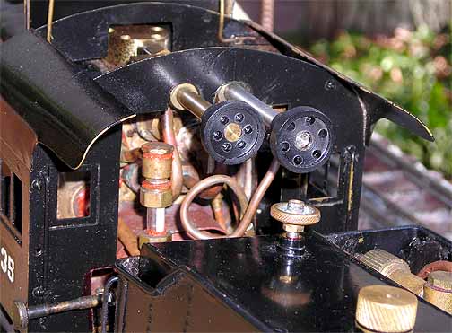
All the detail parts were handmade, as there are very few available for gauge one, 1:32 scale. Components like the steam domes and pumps had to be made from brass shapes. Tender trucks are my own resin castings. The keystone number plate on the front was fabricated from brass and cut out with a fret saw. I copied parts from Aster kits, which provided ideas for making many of the operating components.
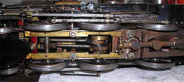
The cylinders are on the outside, like the prototype's, but the inside valves are round D-valves. The design is from the G1MRA “Dee” plans. Dummy valve linkage is designed to look like the prototype.
Operation
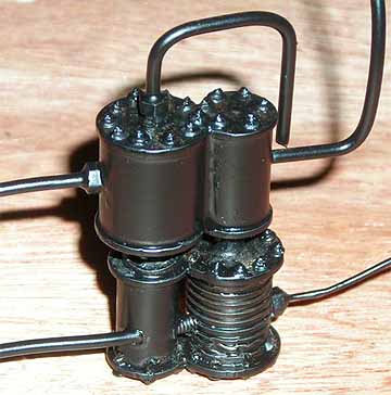
Running this engine is like running most alcohol-fired engines. You add water, steam oil, and fuel. The lubricator is a displacement type, with dual chambers to feed each valve independently. The fuel is held in the tender in a removable tank.
Once the engine is in steam, you can keep it in fuel and water as long as you like. Water can be pumped into the boiler by the tender pump. The engine was designed to have an axle pump, but this had to be removed to allow clearance for enlarged burners.
The boiler still needs work. It was fitted with two fire tubes. These should have been larger or there should have been three smaller tubes to make more steam. The burner size was increased to keep up the steam pressure. This is an area I intend to change at some point . For now, it does run but it could make a little more steam. The target PSI was 60, but it will barely maintain about 30 PSI, with two P54 commuter cars.
[As an addendum to the boiler problem, since I originally wrote the above, I have changed the wick material to fine stainless-steel mesh, resealed the firebox, and fixed some leaky fittings. All of these changes improved the performance. At Larry Herget's steam up in the fall of 2011, I was able to keep the engine in steam for 25 minutes, with a break for water, then another 25 minutes, when the fuel ran out.]
I made extensive use of O-rings to seal many of the steam joints. As an experiment, some of the steam fittings use a flange-type of fitting rather than a union-type of connection. These did work okay but still required sealing compound.
Water can be added directly into the boiler at the start by removing the safety valve. Once under steam, the hand pump in the tender does all the rest of the work.
The only commercial parts are the pressure gauge from Walsall Model Industries, driving wheels from Mark Wood, and the builder plate by Diane Carney.
Below is a video of the G5 in action. If, for some reason, you can't see it, click here.
|
|
|
| Builder | Ernie Noa |
| Date completed | 2008 |
| Gauge | 45 mm (gauge 1) |
| Scale | 1:32 |
| Boiler | JvR type C, two fire tubes |
| Fuel | Alcohol |
| Blow-off pressure | 60 psi |
| Cylinders | Two brass 1/2" pistons with Viton O-rings in bronze cylinders, sleeved with K&S tubing |
| Reversing gear | Slip eccentric |
| Lubricator | Displacement, dual chamber |
| Weight | 14 pounds, engine and tender |
| Dimensions | Length, 27“; width, 4“; height , 5-3/4“ |


Back to Sidestreet Bannerworks
Click here to find out how your engine can be featured!
This page and its contents
Copyright Sidestreet Bannerworks, 2011