


by Marc Horovitz
I’ve always liked Ted Stinson’s plans, as published in Garden Railways magazine. and have always wanted to build some of them, but finding time has always been difficult. In all the years the plans have been running, I have only managed to build one (#18, the barge). The Model T truck, which first appeared in the October 1998 issue of Garden Railways as a stake-side, and which will appear again in the August 2004 issue as a tanker, has always attracted me. I thought it would make a good railtruck.
Another thing that has always appealed to me, but which I had little experience in, was working with tinplate. This is what “tin” cans are made of—sheet steel plated with tin. In some parts of the country, you can still find tinplate in sheets, but not where I am. I am reduced to cutting apart old food cans and flattening them out, which I’ve been doing for some time now. I’ve accumulated a pretty good stockpile of tinplate, some printed and some plain. Of all the cans out there, gallon containers of olive oil provide some of the best material, as far as size and flatness.
In retrospect, it was inevitable that the Model T truck plans and the stockpiled tinplate would meet, and finally they did. The truck, as presented in the plans, was to be made of bits of wood and cardstock. I copied the plans, cut out the pieces, sprayed their backs with adhesive, and stuck them to the tinplate sheet. I found that I could easily cut out the metal parts with a good pair of scissors.
Traditionally, tinplate is soldered together. Usually, one side of the tinplate will have printing on it or, on the inside of some cans, a protective coating of some sort. This must be removed for the solder to stick (I used a Dremel tool with an abrasive disk to grind away the coating). Both parts to be joined have to be “tinned” first—that is, a thin layer of solder must first be applied to the areas to be joined. The parts are then held together and the iron applied to the joint. If all is well, the solder melts and the joint is made. Solder is never applied directly to the joint, but is picked up on the end of the iron, then transferred to the joint. It takes a little practice, but is great fun and the results are very satisfying.
Following the instructions as much as possible, I started with the fenders. These I cut from a can, scraped off the printing, and soldered a bead around the edge. My small, 35W iron worked well for this (and for the rest of the project , too). With some difficulty, I soldered the quarterpanels to the fenders. These later came off because they interfered with the railroad wheels. (Click on the image for a bigger picture.) ![]()
After the fenders came the hood. Bending the parts was mostly done in the vise. I clamped the piece in the vise with the edge to be folded just at the top edge of the jaws. Then, using a mallet and a piece of scrap wood, I beat the part over the vise jaw. If the jaws got in the way because of a previous bend, the part could usually be supported in the vise with a piece of hardwood.
The hood was fairly straightforward, but the grill was a stumper. I didn't want the tedium of making a finely crafted grill for a project that, at that moment, I didn't know would work out well or not. In the end, I just ran a piece of tinplate through one of those tube squeezers used to make corrugated siding. A radiator cap was turned on the lathe from a small piece of hex stock.
The main frame of the truck was intended to be made of plywood. I just folded a piece of tinplate to the same dimensions and soldered the hood to it. The fenders I soldered to supports made of some flat wire I had around.
Then came the wheels and axle. The front axle was made of bits of brass. The dummy springs were made of the same flat wire as the fender braces. The wheels I made from brass. The hubs I turned from round stock and the rims from brass tubing from the scrap bin. I cut the webs from 1/16" plate. Decorative holes were drilled, as were the holes for the hubs. Then I put each web on the lathe and turned it to size, forming the edge into a flange and making a slight recess so that the rim would seat concentrically. Some rivets were added for texture and each wheel was soldered together with soft solder using a torch.![]() Once the wheels were finished, I mounted them on the front end.
Once the wheels were finished, I mounted them on the front end.![]()
The cab floor was a simple matter of folding the metal to the shape of the specified plywood floor. The seat was also relatively simple. I scored it to crudely represent upholstery. The cab I cut out according to the plan, folded it up, and soldered it together. ![]()
Then I soldered the cab to the floor around the edges, and also to the hood, which was a little tricky. This was sort of a turning point, as the unit now looked like a real vehicle.
The headlights (which are not the proper shape) were made by rolling strips of tinplate around a dowel, then soldering backs to them. I was completely flummoxed by the louvers on the sides of the hood and ended up just leaving them off. A piece of real glass forms the windshield, which is held in place by tinplate clips.
The underbody components, which were to have been made from bits of wood, I also fabricated from tinplate. I designed paper patterns on the computer, which, when cut out and folded, would provide the desired shape. I printed them out, stuck them to the tinplate, and cut them out with scissors. All joints were soldered for strength, and the finished pieces were soldered into their respective positions under the frame.![]()
For power, I’d been experimenting with clockwork motors. The plans, as printed, called for the truck to be a stake-side. However, this wouldn’t conceal a clockwork motor, so I decided to build a van body. To support the body, I extended the frame with some tinplate channels, them made a bed to form the floor of the van body.![]()
The van body I again designed on the computer, printed out the drawings, and transferred them to the tinplate. The roof was carefully rolled to conform to the plans. 
I marked out the holes in the sides for the doors, cut them roughly to size with a Dremel tool and an abrasive disk, then squared them up with a flat file. The doors are simple rectangles with the edges folded in for depth and strength. They slide on door rails folded up from tinplate and soldered to the van sides.
The clockwork motor I used in the truck I picked up on eBay. I reworked it, making new frames for it and rearranging the gear train a little. I removed the governor, but left the governor gearing in place. This provides enough governing power so that the truck doesn’t run over-fast. The drive system is Serv-O-Link Delrin chain and sprockets, geared up 1:5 to the axle. ![]()
The clockwork motor had no key, so I made one out of K&S square tubing. I found the size that best fit the winding shaft, then telescoped the next size over it for added strength. I drilled a hole through the tubes at one end and soldered in a length of 1/8" welding rod for the handle. ![]()
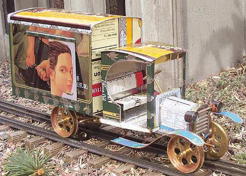
Once the truck was running to my satisfaction, I installed the van body. It is held in place with four 2-56 screws and can be removed at any time. To wind up the motor, you open the van door on the right side, insert the key, give it a few twists, and off you go. The truck makes a satisfying rattly sound as it heads down the rails. 
The truck has very little power, but will move itself around 60 feet, coincidentally just about the same distance between two of the stations on our Ogden Botanical Railway. Only one wheel is powered, to keep the wheels from binding on curves and reducing the run.
My original intention was to paint the finished truck, but the consensus of those who have seen it is to leave it au naturel. I’m still deciding.
.
Go to the Sidestreet Bannerworks home page