Back to Sidestreet Bannerworks
Click here to find out how your engine can be featured!
.


A Model-T Ford rail motor
by John Riley
Rockledge, Florida USA
May, 2010
The notion for this steam-powered rail truck originated with Mel Ridley’s article in the July -August 1985 issue of Garden Railways. In his article, “Steamed Goose Dim Sun,” Mel suggested building a rail truck using a Mamod stationary steam boiler, with its oscillating engine driving the rear wheels via a chain drive. This as a play on the DRG&W “Galloping Goose” type of rail motors.
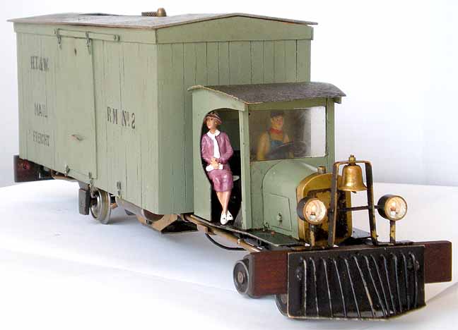
The October 1998 issue of GR published Ted Stinson’s plan set #35 for a 1927 Ford Model T truck. The vision of a T-Model rail motor ambling down the track with a steam plume issuing from its overheated radiator was appealing. A small boiler and oscillating steam motor could be hidden under a delivery truck type body.
During the early years of the 20th century, small, cash-strapped rural railroads resorted to “home built” rail trucks and cars for maintenance of way and to provide service for light freight and passengers and, in some cases, their US Mail delivery contracts. So the HT&W RR's rail motor project could be considered to have prototypes in the twelve-inches-per-foot world.
The Rail Motor
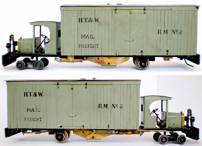
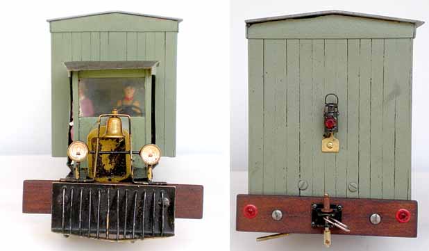
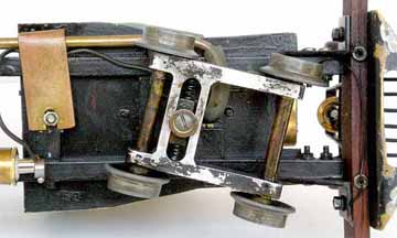
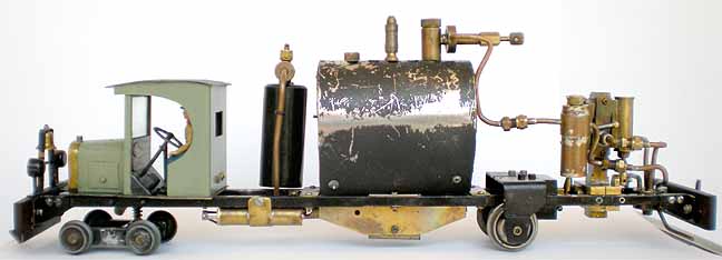
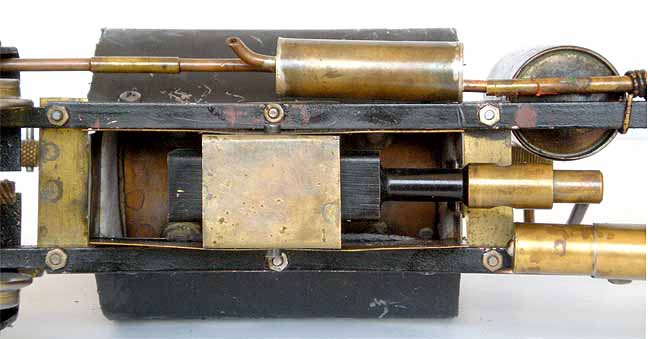
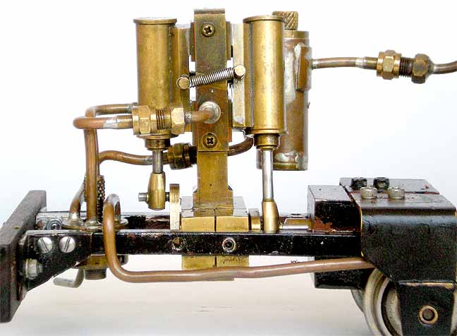
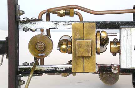
The truck cab, radiator, headlamps, and hood were fabricated from brass; a microscope slide was used for the windscreen; wood for the dash board and seat; and 1/4" aluminum for the frame. A four-wheel truck, rolling on regauged Lionel freight-car wheels with reduced flange diameter, supports the front end. Power is provided by a pair of double acting oscillators (originally made as after market improvements for Mamod engines), which drive the rear wheels through reduction gears obtained from a garage-sale Zebco fishing reel. The use of Zebco gears was suggested by Larry Herget. The shrouded porcupine pot boiler is heated by a butane fired ceramic burner, also an after market Mamod upgrade, which gives about a 20 minute run.
The shrouded 2"-diameter x 4-1/4" pot boiler sports 14 “porcupine” quills in three rows and has a single center stay that extends through the end caps to provide a means for mounting. There are three bushes to provide for a Goodall valve, a Charlie Mynhier-style safety valve, and a regulator. There is no pressure gauge or water-level gauge. A displacement lubricator provides lubrication and a reversing valve sits below the oscillator. Steam passes through an oil separator, which looks like a muffler, and is then exhausted from the radiator cap. A lift off delivery-truck body hides power plant during operation. Headlights and a tail light are provided for night operation.
The run
The run took place during a well attended steamup on Norm Saley’s elevated track in Orlando, Florida. The day was sunny with a pleasant breeze. The temperature was in the high sixties, a bit cooler than normal for central Florida in mid March. The truck body was removed for access to the gas tank, boiler, and lubricator.
The gas tank was filled in the usual fashion. The boiler was filled with distilled water to about 75% of its 95cc capacity. The lubricator does not have a drain, so the last bit of gunge remaining from an earlier run was sucked out with a syringe and fresh steam oil added. Lubricating oil was applied sparingly where needed.
With preparations complete, the rail motor was placed on the track and the gas turned on and lit. After three minutes steam was starting to spit from the safety valve. The regulator was opened and the reversing-valve lever was set for forward operation. With water and steam spitting from between the port-block and cylinder-block faces, the ossies started to turn over.
The spitting subsided as all the metal came up to temperature. After the unit had run a few feet in forward and reverse, it was stopped and the delivery-truck body was put in place. The reversing-valve lever was set for forward operation and the rail motor set off at a sedate pace around outer loop of Norm’s double track line.
After a couple of circuits the unit was run back and forth on a section of the track where the light was best for photographing the steam plume from the radiator cap. Picture taking completed, the rail motor was sent on another circuit of the track. By then 15 minutes had elapsed the fire was shut off and the run ended.
There was still gas in the butane tank and a little water left in the boiler. Usually, the run is extended by adding water through the Goodall at the 15 minute point and letting the run continue until the butane is exhausted. But the picture-taking session was a departure from normal operating routine and it was time to quit while all was still going well.
|
|
|
| Builder | John Riley (USA) |
| Date built | 2002 |
| Gauge | 45 mm (gauge 1) |
| Scale | 1:20.3 |
| Boiler | Pot boiler (with 14 “porcupine” quills) |
| Fittings | Safety valve, Goodall valve, regulator |
| Fuel | Butane |
| Blow-off pressure | 35 psi |
| Cylinders | Two, double-acting oscillators |
| Reversing gear | Rotary valve |
| Lubricator | Displacement |
| Weight | 5 pounds 2 ounces |
| Dimensions | Length, 17-1/2"; width, 4"; height, 5-1/4" |

Back to Sidestreet Bannerworks
Click here to find out how your engine can be featured!
This page and its contents
Copyright Sidestreet Bannerworks, 2010