Back to Sidestreet Bannerworks
Click here to find out how your engine can be featured!
.


BR 55 0-8-0
by Paolo Rognoni
Milan, Italy
Photos by the author
May, 2011
The BR 55 , ex -G8 Prussian group, was one of the most numerous class of locomotives built in Germany at the beginning of the Twentieth Century. More than 5,000 were built (more than 7,000, if we consider the first G8 series (see picture below).
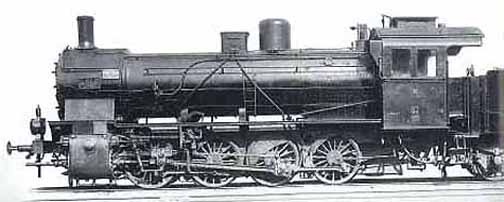
The Prussian G8, predecessor to the BR55.
It was the first four-axle German locomotive. Equipped with two simple-expansion cylinders, it was also the first superheated steam locomotive (Schmidt superheater). Between 1902 and 1913, Vulcan Werke (locomotives builders in Stettin) produced more than 2,000 units. In 1913 the G8 was almost fully revised to improve performance. Specifications of the final design included:
- Power: 1100 HP
- Max. speed: 55 km/h (34 mph)
- Total weight (including tender): 108 tons
- Total length: 18,290 mm.
- Wheel diameter: 1,350 mm.
- Bore x stroke: 630 x 660 mm.
- Max. pressure: 12 bar (175 psi)
Most of these locomotives were coupled with a three-axle tender, with a water capacity of 16,500 liters (4,359 gallons). The last G8 locomotive was produced in 1921.
With the birth of DRG (Deutsche Reichsbahn Gesellschaft = German State Railways Company) in 1923, there was a reclassification of the rolling stock. The G8 group became BR 55.
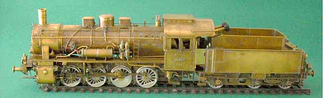
In the picture below you can see the BR 55 No. 4536, built by Hanomag in 1917. Born as G8 No. 5258 Elberfeld, it was later reclassified as previously explained. I chose to reproduce this model because I had the only two pictures where one could see the both sides of the locomotive.
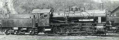
BR 55 No. 4356, in Opladen, 1932.
The model
I'm 43 and have always lived near a railway station. When I was a child, I saw a real steam locomotive for the first time. It was love at first sight ! Into my child's mind came the mission of building a live-steam model. Some years later, I received a book as a gift, where I discovered that live-steam models really existed!
I started to build this locomotive in 1986 and I spent 20 years and more (not continuously) to complete it. Now, many years and many "starts and stops" later, the model is almost finished. Only the painting remains.
In 1985 I bought a Fleischmann catalogue. In it I saw a BR 55 model, very beautiful, and I decided to reproduce it. But the catalogue did not provide enough information to build it. I needed much more, so I visited an important modeling exhibition in Milan, where I found some copies of the magazine Eisenbahn Journal. One of these was a special number about the BR 55 locomotives. I had found what I was looking for.
Over the years, I bought many other magazines, where I found pictures and drawings about the fittings. I got much more information on web sites, especially Aster's. Sometimes I managed to find pictures or drawings of fittings on the original makers' web sites ( Westinghouse, Knorr-Bremse, and so on).
I never had detailed drawings -- only a section of the locomotive and the tender. This meant that I had to determine the size of various parts by comparing their proportions with the few known dimensions.
For example, the total length of loco was 15,000 mm. The total length of the loco in the section drawing was 50 mm. The wheel diameter in the section was 8 mm. The real wheel diameter was unknown. So, by extrapolation, 15,000 x 5 / 50 = 1,500 mm.
Furthermore, I don't have a milling machine -- only a small bench lathe, so I had to engineer and make many tools to produce the parts. These tools were often applied on the top slide of the lathe, transforming it in a milling machine. I also discovered that a cyanoacrylate glue (CA) is very good for fixing irregular parts to the faceplate of the lathe for the machining. I'm a mechanical designer, so it was not difficult for me to do everything!
Also, for these reasons I spent more than 20 years of work on the locomotive -- but this is not a job, it's only a hobby !
It's hard to say which was the most difficult part of the locomotive. So I decided to make a little gallery to help explain the machining of some of them.

The wheels are made of three different metals.
 The drivers are made of three different materials: aluminum (which I have come to think was not a good idea), lead for the counterweights, and brass for the hub. The spokes were cut by hand with a jigsaw, equipped with thin saw for cutting metal. Then they were milled on each side to reduce the thickness to 1 mm, using a special jig (right) attached, with some spacers, to the top slide of the lathe, then rotated step by step.
The spokes were then finished by hand using a mini drill with a spherical mill, as well as tiny files, so they look like castings.
Regarding the counterweights, they were melted directly onto the wheels, using plaster molds. Then they were turned to their final shape. The hubs are fixed from the rear with a couple of 1.6 mm. screws. The crankpins are screwed into place and welded on the back.

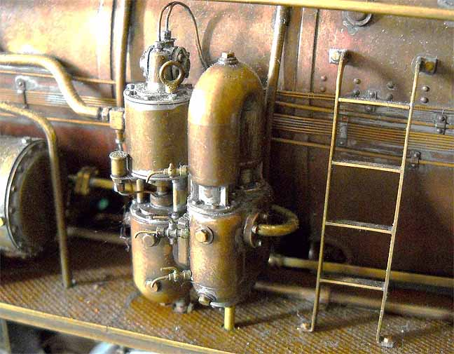
Boiler parts made as experiments.
The boiler is a fire-tube boiler, made of copper, riveted and silver soldered. The photo above shows some "experiments" -- handmade parts produced in the past to gain understanding in how to do it. Many years ago, I bought a book about boiler making (Model boilers and boilermaking by K.N. Harris). This book explained how to shape a copper sheet using a wooden hammer and wood forms. So, using a camping-gas burner for annealing, and some home-made tools, I managed to make the main parts of the boiler (firebox, throatplate, tube plate, backhead, and so on). A 50 mm. copper tube formed the body of the boiler, while a dozen 8mm copper tubes were used as fire tubes .
Then, I assembled all the parts by first riveting them together. Then I applied the fittings and silver soldering everything together. I then tested the boiler, reaching 3 bar (45 pounds) pressure without trouble. The boiler is covered with a 0.25 mm. brass shell, to reproduce the original design.
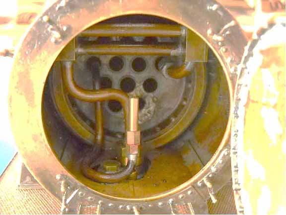
A view inside the smokebox. The fire tubes are clearly visible.
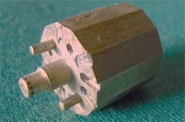
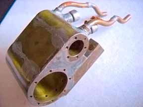 The photo at right shows a prototype cylinder, made some years ago. At the beginning it was a brazed assembly but this solution was not good. The connections have broken themselves. So, I decided to make a cylinder block from a brass block, milled on a CNC milling machine (in the workshop where I worked some years ago). I then pressed two cylinder liners into the bored holes -- one for the piston and one for the valve spindle. Both have a series of radial steam inlet/outlet holes, 1mm diameter. I pressed a 3/4" sphere into the piston cylinder liner to obtained a lapped surface, while the valve-spindle cylinder liner was bored. Finally, the finished cylinders were covered with a 0.25mm. brass shell, as the original.
A series of 1.6mm. screws were used to attach the cylinder covers. I used small O- ring gaskets for pistons, rods, and covers, and I built and installed working drain cocks.
As you can see in the photo below, there are a lot of rivets on the locomotive and tender. They were made and positioned one by one, to create a realistic effect. Every rivet has been soldered on back. Each rivet's stem is 0.5/0.7mm diameter, while the head is 0.8/1mm.
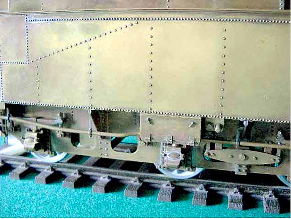
Each rivet was individually placed, as per the prototype.
The run
I tested the locomotive many times on a test bench. Recently, though, I bought a circle of track with a diameter of about six meters, so I can finally run the engine.
I filled the lubricator with 15cc. of oil, using a syringe. The boiler was filled to 80% with water (about 200 cc) using an external pump that I made. The capacity of the tender is 100cc of water and 100cc of alcohol.
Working pressure is reached in about 3-4 minutes using an auxiliary fan. At this point, I open the blower and remove the fan. I open the throttle and the cylinder drain cocks to drain the condensate. Then, as soon as the pressure has came up one or two minutes later, the engine is ready to run.
The quantity of water in the boiler and tender allows about 25 minutes of running. I discovered that it's better to keep the blower open a little bit during the run. On the test bench, the engine has run for about an hour, with two or three refills of water.
Here's a video of the engine in action. If for some reason you can't see it, click here.
|
|
|
| Builder | Paolo Rognoni (Italy) |
| Date built | Completed circa 2006 |
| Gauge | 45 mm (gauge 1) |
| Scale | 1:28 |
| Boiler | Locomotive type -- 12 tubes and 1 superheater |
| Fittings | Safety valve, water glass, pressure gauge, blower, throttle, working drain cocks on cylinders, axel-driven pump, superheater |
| Fuel | Alcohol -- chicken-feed system in tender |
| Blow-off pressure | 1.5 kg./cm2 (21 psi) |
| Cylinders | Two double-acting with piston-valves |
| Reversing gear | Heusinger (similar to Walschaerts), with screw reverser |
| Lubricator | Roscoe displacement |
| Dimensions | Locomotive, 400 mm; tender, 245 mm |
| Weight | Locomotive, 4.4 kg; tender, 1.3 kg |


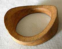
Right: The wooden former the author made to help with forming the steam dome flange.


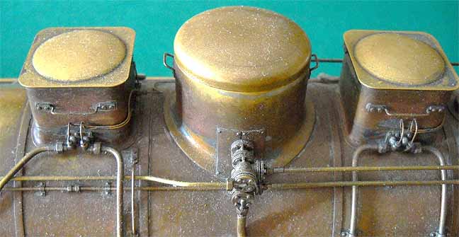
Above: Each lamp is hollow and sits over a bulb. The parabolic reflectors in each lamp were stamped from thin metal.


Back to Sidestreet Bannerworks
Click here to find out how your engine can be featured!
This page and its contents
Copyright Sidestreet Bannerworks, 2011