Back to Sidestreet Bannerworks
Click here to find out how your engine can be featured!
.


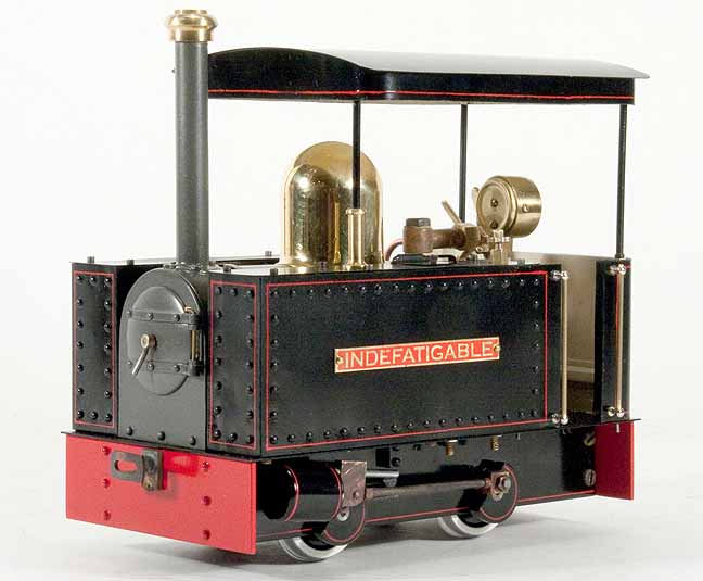
Indefatigable
by Marc Horovitz
Denver, Colorado
Photos by the author
May, 2012
The design
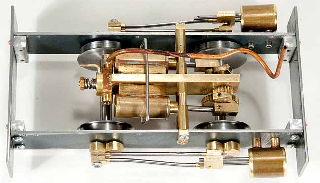
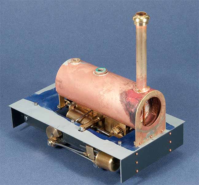
I like to design my own engines and I like small, narrow-gauge beasts. Some years ago I designed a little steam motor that I have used successfully in two or three engines, including the monorail engine and one of my trams, so decided to base the new design on that motor. It is a self-contained unit that has a pair of double acting, oscillating cylinders and a rotary reversing valve. As such, it can be incorporated into a locomotive in a variety of different ways. Since oscillators like to run fast, I intended it to be geared down to the driven axle at least 2:1.
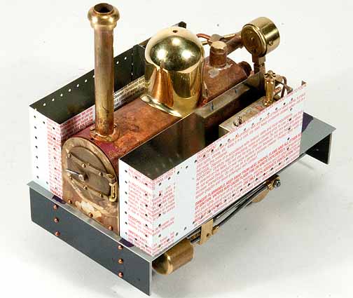
On my monorail engine, the steam motor was right out in front, mounted horizontally. On the tram engine, I mounted it vertically in the cab. On this locomotive, I decided to mount it between the frames (unprototypically) and gear it to the front axle. Then I would hide the steam motor with side tanks and make a pair of dummy cylinders to mount outside, in the usual place.
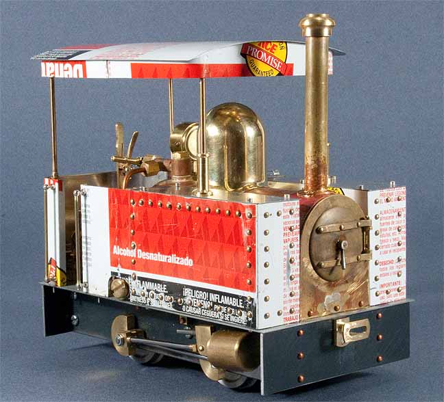
Since the steam motor occupied all the space between the frames, that obviated the use of an alcohol-fired boiler, with wicks underneath. With a single flue, gas-fired boiler, I could put the gas tank in a side tank.
Because the engine is freelance, and because I like British narrow gauge, I patterned it after UK practice. It would have full-length dummy side tanks, a hinged smokebox door, and a big brass dome over the safety valve. The lubricator could sit next to the boiler, behind one of the side tanks.
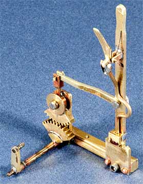
The reversing valve would be actuated by separate lever in the cab, via a fairly elaborate (but fun) geared system that was done to reduce the lever throw necessary to actuate the valve. I put a big roof over the engine to give the driver protection from the hot Colorado sun.
The build
With the design pretty much complete, construction commenced. The steam motor was the first order of business, since I already had drawings for most of the parts. I like to draw up my designs fairly completely (at least so I can understand them), which gives me a road map when I get to the workshop and makes for a lot less wasted time trying to decide how to do things.
In due course, the steam motor was finished and running smoothly on compressed air. I then made the frames from 1/16" steel plate, then the wheels and axles. I made my own gears -- something I enjoy doing -- and mounted the little one on the steam motor and the big one on the axle.
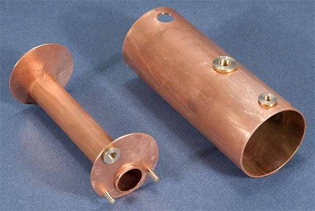
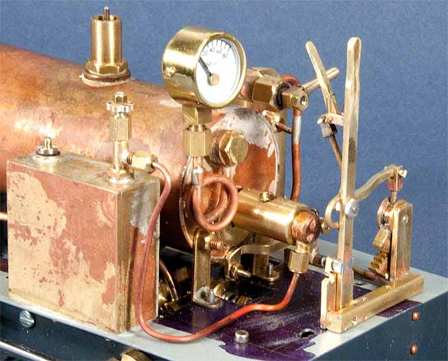
Once the chassis was working smoothly and the dummy cylinders and rods were in place, it was boiler time. This I made from a piece of copper plumbing. It has just three bushings: one for the safety valve, one for the pressure gauge, and one for the throttle turret. Assembly was straightforward and I silver soldered all the pieces together, then pressure tested it at 100 psi. All was good.
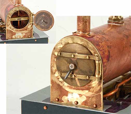
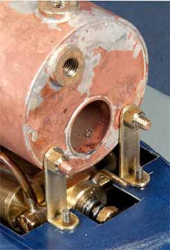
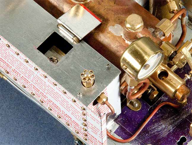
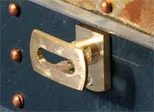
With the boiler finished, I moved on to the smokebox front, which involved a hinged door that opens for lighting the fire. This was an interesting mini-project in itself. The hinge straps are riveted to the door and the handle actually works as a latch, similar to a proper dart (but there is just one handle).
With the boiler done, I mounted it to the chassis. It was starting to look like a locomotive. I made the boiler fittings, including the throttle valve, the safety valve, and the lubricator. I set the safety to blow at 40 psi. Gaskets for the various bits were cut from a sheet of automotive gasket material that I acquired along the way.
Next came the dome, which began life as a 1-1/4" round brass bar. I cut the hemispherical top end on the lathe with my ball-cutting tool, then recessed the bottom end, leaving a fairly thin wall. I scooped out the bottom to fit the boiler contour, holding the dome in my milling vise and using a fly cutter to do the profiling. I then heated the dome to red heat to anneal it. With the aid of a hammer and a piece of 1" dowel, I beat out the flare at the bottom. When I got it to fit properly, I polished the dome to a high gloss with a buffing wheel.
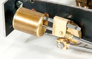
I had some difficulty with the burner. I built one based on a published design but it was unsuccessful. With the help of a British friend, John Turner, I built a second one, which performed very well indeed. I used an Accucraft jet, turned down and soldered into a small housing to reduce its overall size.
The gas tank is made out of a section of large, square brass tubing that I had on hand. I made the control valve and used a filler valve from one of Harbor Freight's cheap micro-torches.
The engine was now together and could be bench tested. This was done in the usual way, on blocks, and all seemed well. I should mention that I did a very brief test without steam oil in the lubricator. More about this later.
Then it was time for the sheet-metal work. I'm a big proponent of the use of tinplate (tin-can metal) so decided to use it for all of the sheet work. At around .008", it's thinner than than the brass I'd ordinarily use, which is around .020" thick. I was a little concerned that the tinplate would be too flimsy but, as this was a small engine, it might be OK. In the end, it worked just fine.
I had a bunch of empty alcohol cans rescued from one of the Diamondhead steamups, so it seemed fitting to use those on this enging (even though it's gas fired). I cut all of the parts with scissors and folded them up using methods found on the Tinplate Girl web site. I drilled a lot of holes for dummy rivets, which took the form of brass escutcheon pins soldered in place. The tank tops, also tinplate, are screwed on. The rest is soldered. Tinplate's a wonderful material to work with and solders like a dream.
At long last, the engine was finished, with the exception of the dreaded paint job, a task that is guaranteed to put me into a cold sweat at the very thought of it. However, I tackled it. Despite some initial sebacks that involved stripping some parts and starting all over, the job was eventually finished. If you don't get too close, it looks acceptable. The red lining was done with a ruling pen (bow pen) using Humbrol paint thinned with lighter fluid.
I decided to have another go at etching name plates. I had done a little acid etching before with mixed results. I'd heard about galvanic (or electrolytic) etching, so decided to give that a try. I'm not going to go into the details here -- check out this web site to learn more about the process. I found that this method worked well, is safer than acid etching, and less messy.
Running
It was finally time to give it another test run. I decided to do this again indoors on blocks. I filled the boiler with water, the tank with butane, and the lubricator with some treacly steam oil a friend had given me. I lit the fire, pressure came up quickly, and I opened the throttle. The engine seemed like it wanted to go but was struggling mightily. The wheels went around but very slowly, even at full throttle. Something was obviously amiss. It had run very well before -- fast and free. As Sherlock Holmes said, "Eliminate all other factors, and the one which remains must be the truth." The only thing I could think of was the steam oil.
I stripped the engine down yet again, cleaned out the lubricator, steam lines, and cylinders (messy job!), then reassembled it. I filled the lubricator with some much lighter oil and lit it up again. Yep, that was the problem. This time it ran beautifully.
It runs well on the track, too. Being a small engine, steam comes up quickly. It will run for around 15-20 minutes, which I think is good, given its size and the fact that water cannot be added during the run. The gas consistently outlasts the water, so I have to keep an eye on it when I think it's getting low. It's surprisingly strong, too. It had no trouble pulling three heavy coaches, about the limit of a prototype engine of its size.
You can see it running in the video below. (It's throttled back when pulling the coaches.) If, for some reason, the video doesn't work, click here
|
|
|
| Builder | Marc Horovitz (USA) |
| Date completed | March, 2012 |
| Gauge | 1 (45mm) |
| Boiler | Single flue |
| Fittings | Safety valve, throttle, pressure gauge |
| Fuel | Butane |
| Cylinders | Two double-acting oscillators |
| Reversing gear | Rotary valve |
| Lubricator | Displacement |
| Dimensions | Width, 3.7"; length, 6.125"; height, 5.8" |


Upper right: The burner, shown here upside down. When installed, the flame will burn on the bottom.
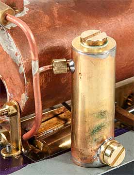
Right: The dead-leg displacement lubricator, installed on the footplate and plumbed into the steam line.


Back to Sidestreet Bannerworks
Click here to find out how your engine can be featured!
This page and its contents
Copyright Sidestreet Bannerworks, 2012