Back Locomotive Gallery homepage
Back to Sidestreet Bannerworks
Click here to find out how your engine can be featured!
.
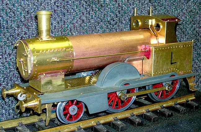
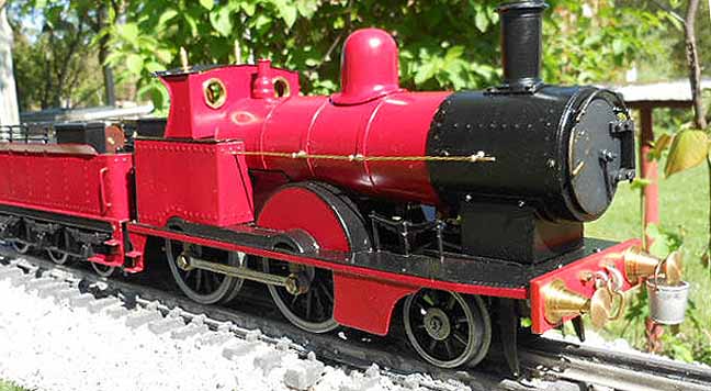
The finished locomotive on the author's railway.
Building the Precedent 2-4-0
by Larry Herget
DeSoto, Missouri Photos by the author
July, 2012
In January, 2009, at the National Steamup in Diamondhead, Mississippi, I admired an Aster "Jumbo" that was sitting on the counter in the steaming area. I returned several times during the show to look at the engine. Finally, I took a few photos of it and measured critical dimensions -- length, width, height, and wheel diameters -- and wrote them in the convention's giveaway notebook.
Upon arriving home and unpacking, I came upon the notebook and decided to unload the camera to see how the photos came out. I printed the photos and started sizing everything up using a ratio I have developed. Then I started to collect parts out of my huge store of junk.
I started on this loco right after I had finished the Precursor. It was built in November and December of 2009, as I wanted to run it at Diamondhead in January of 2010. I ran it there and compared it to one that was also there. My engine was pretty close to the other, given that I was just working from a few dimensions and some photos. Thanks go to Will Lindley for a few detail photos he sent me.
Below are some pictures of the engine during construction. The first run was on a cold, windy day. I was freezing and so was the butane. I had to go inside to get some warm water for the tender so the gas would flow.
Here's a brief video of the engine's first run. If, for some reason, you can't view it, click here.
Specifications
Builder
Larry Herget (USA)
Date completed
November-December 2009
Gauge
1 (45mm)
Scale
Nothing in particular
Boiler
Single flue
Fittings
Safety valve, water glass with blowdown, throttle, Goodall-type filler valve under the dome, lubricator on left running board
Fuel
Butane
Cylinders
One double-acting oscillator, geared 3.43 : 1
Reversing gear
Pick it up and turn it around
Lubricator
Displacement
Blow-off pressure
40 psi
Dimensions
Buffer to buffer, with tender, 18-1/8"; width, 3-1/8"; height, 4-3/4"
Weight
7 pounds, 4 ounces
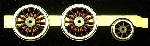
Wheels and a single frame laid down flat show the basic layout of the chassis. Work progressed from this point.
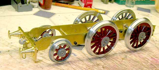
This is the chassis the next day, with the wheels turned to G1MRA specs and placed temporarily on their axles.
The engine needed some side rods, so I made them up from brass bar stock, seen here being milled.
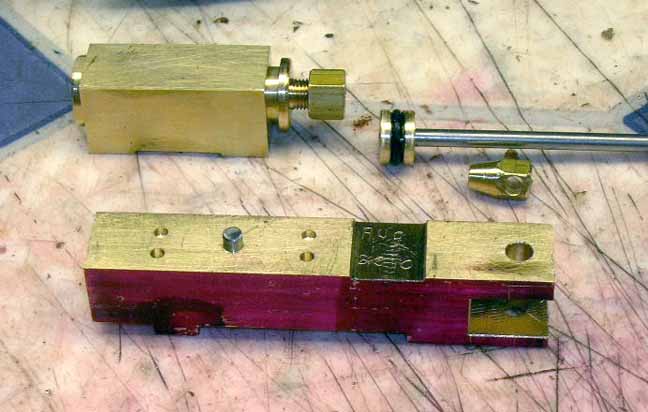
The locomotive has one oscillating cylinder. The basic motor parts are shown here. Yes, it has a square cylinder (no, notinside -- just outside.) The bore is micro-honed, with a diameter of .437" and a .660" stroke. The ports are jig bored from the crankshaft with home made tooling -- no guessing that way.
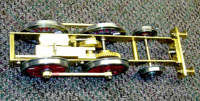
The steam motor, mounted in the chassis. Gears are Boston, 3.43 : 1 ratio. A 14-tooth small gear meshes with a 48-tooth large gear. Both are 3/16" wide (no, I won't wear them out).
At this point it was time to test-run the chassis on air and break it in a bit. I set it up on some blocks in the garage and hooked it up to the compressor using a drip oiler tool line. I let it run slowly for one hour. Everything was smooth after the run in.
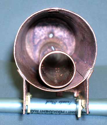
Left: A view of the rolled-copper boiler shell without the backhead. You can see the lap seam at the 4 o'clock position, the flue, and the phony firebox below.
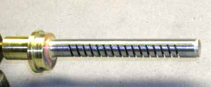
Below: The energy converter (i.e., the poker burner) is 3/8"-diameter stainless steel. It uses a #6 jet.
All of the engine's body work is made of .025" brass with pressed-in rivet detail.
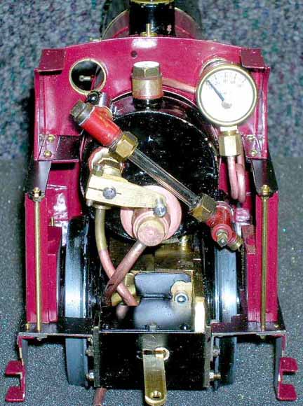
The cab with the roof removed. The water glass has a built-in blowdown valve, seen at the lower right.
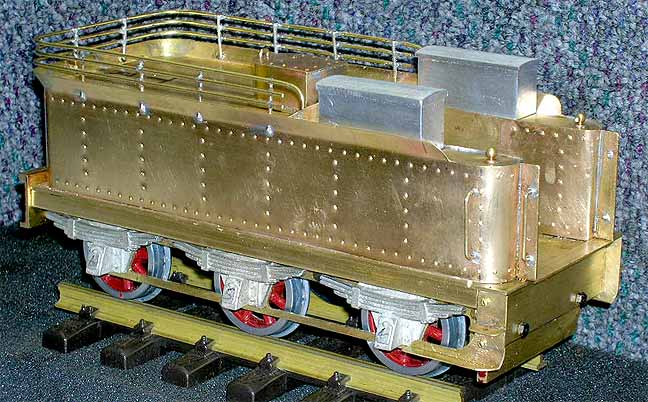
The tender was built next, to house the fuel supply (butane). It, too, is made of .025" brass, with pressed-in rivet detail. All soldering on the tender was done with 40-60 soft solder. Tender wheels are reproduction Lionel Standard Gauge 400E pilot wheels, re-contoured to G1MRA specs. Journal boxes are made of white metal that I spin-cast from my own pattern.
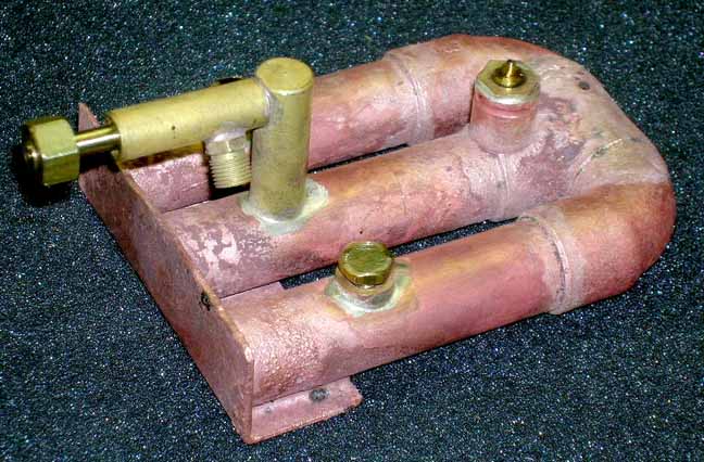
The fuel tank is made of commercial copper elbows and pipe, with brass fittings and bushings for the filler and control valves. Copper parts are phos-copper brazed and the brass-to-copper connections are all silver soldered.
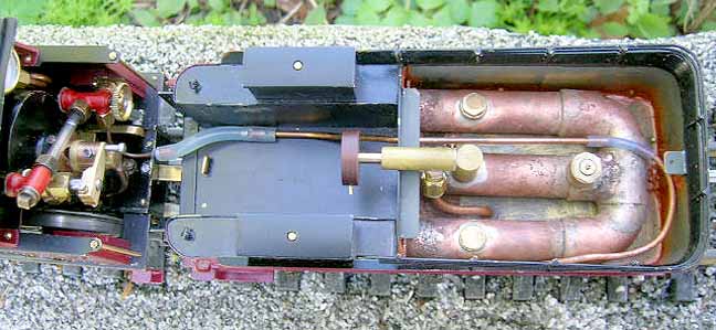
The fuel tank installed in the tender. There is a water-bath warmer for the butane for cold-weather running. This comes from the blowdown valve on of the water glass. The blowdown is routed through the small copper line, which can be seen running back from the cab area.
Another shot of the completed locomotive.
Back Locomotive Gallery homepage
Back to Sidestreet Bannerworks
Click here to find out how your engine can be featured!
This page and its contents
Copyright Sidestreet Bannerworks, 2012