Back to Sidestreet Bannerworks
Click here to find out how your engine can be featured!
.

Ryan Norton's
Crackpot contractor's locomotive
by Ryan Norton
Johannesburg, South Africa
Photos by the author
March, 2013
The contractor's locomotive was an important item for many engineering works, quarries, brick yards, etc. While fineness of finish and economy in operation were not important requirements, strength of parts and attachments were exceedingly important to enable the engine to work regularly over rough track and to withstand the shocks and rough handling to which it was inevitably subjected.
In a majority of cases, the engines used by contractors were ordinary locomotives of small size, with piston rods connected directly to the driving wheels by connecting rods. However, there were a few geared locomotives that showed some advantages over the other type. A good example of a geared-locomotive designed for contractors' use was built by the John F. Byers Machine Co., of Ravenna, Ohio.
Description
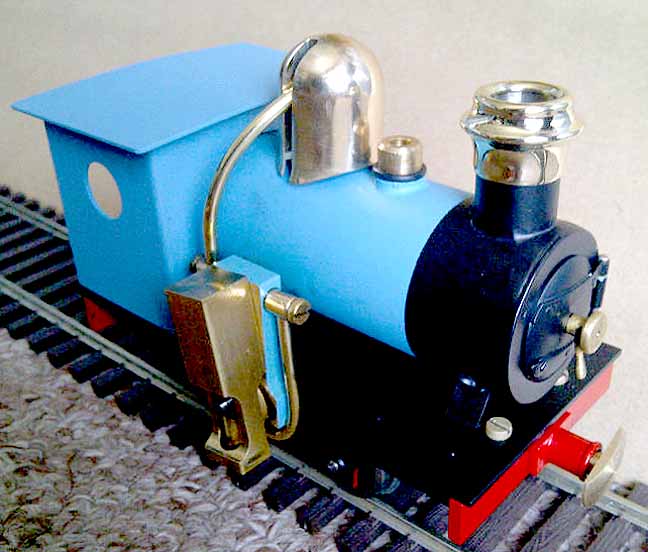
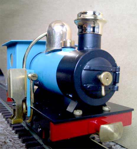
This engine was based on a design by E. Glaser for Cracker. Deviations to the cab, fuel source, and smokebox were made to enhance the look of the locomotive, giving it a more prototypical appearance than the original design. Everything was scratchbuilt, including all of the gears, which were made on the lathe using a shaping method. The smoke box door is fully functional, with a dart and relevant appurtenances.
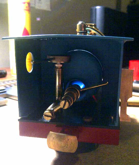
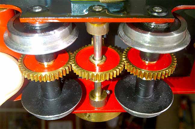
The actual steam motor of the loco is a wobbler cylinder, with a piston connected to a crankshaft that has a pinion gear attached. This pinion drives a central gear that meshes with two additional gears, one on each axle. The reduction in the gear ratio is about 4:1, which enables the loco to travel at more realistic speed for its size.
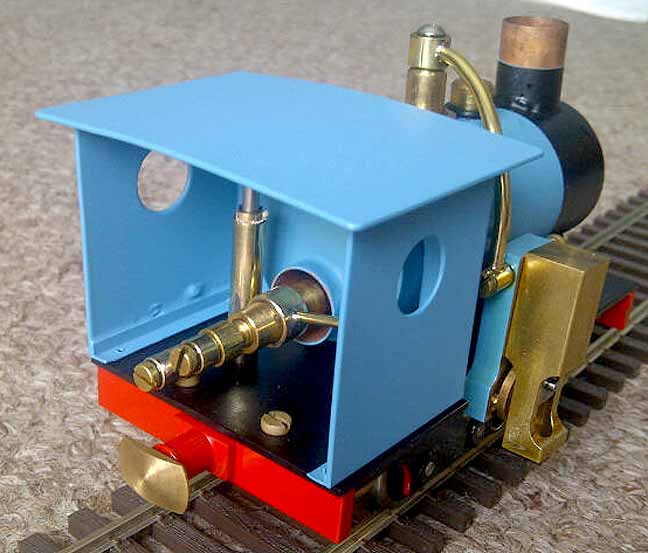
The loco is gas powered and carries a small gas cylinder under the footplate, with access to the Ronson valve through the frame on the right-hand side, under the cab.
Operation
The boiler is filled with about 30 ml of water through the non-return Goodall valve situated in front of the “steam dome” on the boiler. (There is no gauge glass, so this amount has been determined by trial and error.)
The small (too small) butane reservoir beneath the cab is filled via the pillaged Ronson valve, located on the outside of the frame.
To light the burner, the smokebox door is opened and the fuel needle valve is opened until the sound of gas escaping is heard. A match is then administered to the chimney and a clear “woof” is heard as the fire catches.
Steam pressure builds up and, within minutes, pushes the cylinder off the stand with a hiss. If the flywheel is then given a bit of a push in the forward direction, it comes to life and puffs of down the track.
A typical run lasts about ten minutes. This short time is purely due to the small size fuel tank, which was made smaller than the design as it looks more the part than the original.
Lubrication of the piston is performed manually with steam oil to the cylinder-stand interface, and the odd squirt into the steam pipe provides quite enough oil for a couple of runs. All other lubrication on the engine is provided by normal workshop oil from a syringe.
Below is a video of the engine under steam on blocks. If, for some reason, you can't see it, click here.
|
|
|
| Builder | Ryan Norton (South Africa) |
| Date completed | 2012 (begun 2012) |
| Gauge | 0 (32mm) |
| Scale | 16mm = 1'0" |
| Boiler type | Single flue, gas fired |
| Fittings | Steam dome, Goodall filler valve (the wobbler cylinder acts as a safety) |
| Blowoff pressure | Low |
| Fuel | Butane |
| Cylinder | One, single-acting oscillator |
| Reversing gear | None |
| Lubrication | Manual |
| Dimensions | Length: 130mm; width: 60mm; Height: 100mm |
| Weight | 600 grams (around 1 lb., 5 oz.) |
| Steam motor | The single vertical cylinder is of the oscillating type, with momentum maintained by a flywheel on the opposite side. |
| Drive mechanism | Gears on the axles driven by a pinion gear on the crankshaft |
| Interesting features | Fully functional buffers and working dart handles in the smokebox |

Below: The right side. One, single-acting oscillating cylinder powers the engine.


Back to Sidestreet Bannerworks
Click here to find out how your engine can be featured!
This page and its contents
Copyright Sidestreet Bannerworks, 2013