Back to Sidestreet Bannerworks
Click here to find out how your engine can be featured!
.

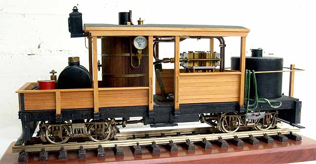
Class A Climax
by Bert Horner
Zwischenwasser, Austria
Photos by the author
June, 2013
At the end of the 1990s I contacted David Bailey of DJB Engineering, after hearing he had produced a kit for a class A Climax. He responded by saying, "Sorry, they are all long finished, but there are a few bits and pieces left." In the meantime, I had been reading an article in Garden Railways that included a drawing of a class A by the late Al Armitage. It was stated that the drawing had been done from the remains of a derelict class A, which was 75% rotted away in a swamp in Alaska, and also from a second one rotting in New Zealand.
No drawings were left after the Climax company closed. The main dimensions could be determined from the remains but the plumbing, etc was guesswork.
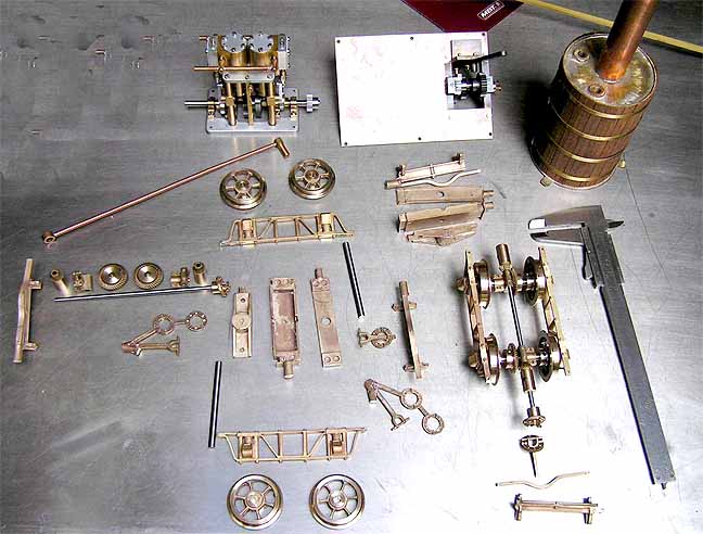
I set about building my chassis using the same materials as the prototype, largely wood, as far as was practical. In the meantime, I had also managed to get a set of trucks and a few other bits from David Bailey, and I set about building my Climax to the drawings from Al Armitage.
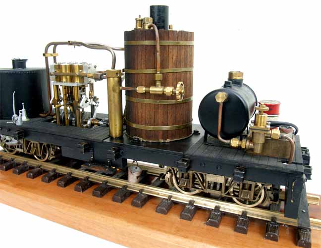
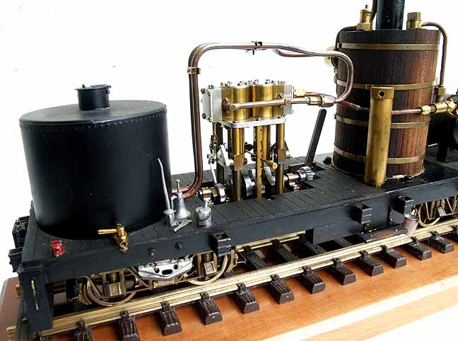
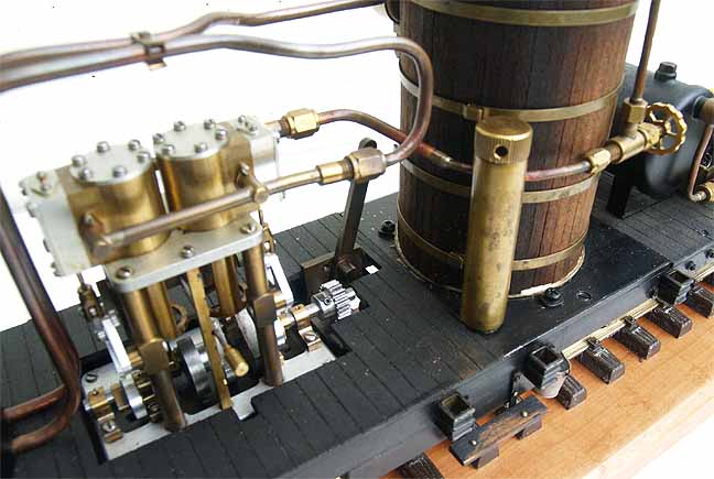
I had a vertical boiler laying around in the workshop, which came from a project that had been shelved for some time, so this was used instead of the T-boiler shown in my drawing. Also, DJB managed to get a two-speed gearbox together for me and I procured one of the recommended Gage 2-cylinder vertical engines.
A ceramic burner was fitted under the boiler and a gas tank on the foredeck, disguised as an oil tank. An expansion chamber was fitted under the rear, round water tank. I joined the parts together with plumbing and, surprise, surprise, my steam-powered chicken shed worked.
Specifications
The engine is manually driven. It is equipped with a sight glass, a pressure gauge, a safety valve set to 40 psi, a hand-wheel steam regulator, a displacement lubricator, a water level plug at the top of the boiler, and a drain plug at the bottom. The reverser is integral with the steam motor and can be notched up. I have only run the engine in full gear because it quickly gets "lumpy" as the reverser is moved towards the middle. Boiler capacity is 180 Ml.
A run
Today is not ideal weather for being out in the garden playing trains. Easter was two days ago and Father Xmas delivered the Easter eggs because it was just too cold for the bunny.
I set my engine up on the treadmill rollers. As usual, I first filled the gas tank. Then I oiled around (not forgetting the steam oil) and I filled the boiler with filtered rain water.
I opened the Cheddar gas regulator, and lit the fire at the chimney. This caught straight away and, in a few seconds, the ceramic heated up, becoming a nice, bright red.
A couple of minutes later the safety was bubbling and the gauge was showing almost 20 psi. I opened the regulator and the pressure gauge showed "0" again. After another four-minute wait the gauge was showing 40 psi and, again, I opened the regulator. The engine turned over a couple times then stopped. I reversed it back and forth until it settled down to even running. Then I opened the water tap on the expansion tank and, with the regulator full open, blew the water out and reclosed the valve.
Having a wood frame, the engine does not get too hot to handle. I lifted it onto my track, hung a short log train onto it, set the gears in high gear, and opened the regulator. After a couple of jerks, the engine got down to steady, slow running the gears making themselves prominently audible. This does not bother me because, if what I have read is correct, class A Climaxes were noisy old bone shakers in reality.
Now because this engine runs slowly and evenly, it is manually regulated, and my present line is very short, I just pour myself a glass of wine and thoroughly enjoy watching it run around my railway. This engine is particularly pleasant to watch because, though the machinery always seems to be very busy, the movement along the track is very sedate. It reminds me of a duck swimming against the stream. Above water, all is still and peaceful; underwater, it's paddling like mad.
After just over 20 minutes, a look at the low level in the water glass shows this run is nearing its end. I have not fitted a Goodall-type valve so I cannot replenish the boiler, so I decided to kill the fire. The engine ran for just about one minute further before stopping on an up-hill curve.
I opened the drain taps on the expansion box in the water tank and the displacement oiler and, with the last bit of steam, blew out the water. Today it is only 6 degrees C (46 degrees F) and I was beginning to feel the cold, so the engine was taken indoors to clean off before putting it into its wooden box. After a long cold winter, it was a real pleasure to have an engine running again. I am now looking forward to better weather.
One point I should perhaps mention is that I had used 3mm piping for the steam line. This caused problems starting. The line from the boiler to the steam motor is long and condensed water was a problem. Increasing the line to 4mm has solved that problem effectively.
|
|
|
| Builder | Bert Horner, Austria |
| Date completed | May 2005 |
| Gauge | 45 mm |
| Scale | 1:20.3 |
| Boiler type | Vertical; ceramic burner |
| Fittings | Gas regulator (diaphragm type -- regulates gas pressure, not the amount of gas); steam regulator ; pressure gauge; water glass; safety valve |
| Blowoff pressure | 50 psi |
| Fuel | Butane |
| Cylinders | Two, double-acting D-valve |
| Reversing gear | Hackworth on steam engine; two-speed gearbox |
| Lubrication | Displacement |
| Dimensions | Length, 435mm; width, 115mm; height, 190mm |
| Weight | 3.85 kg |
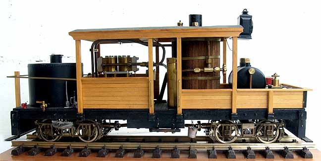
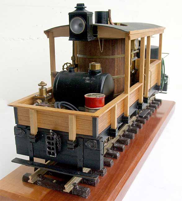


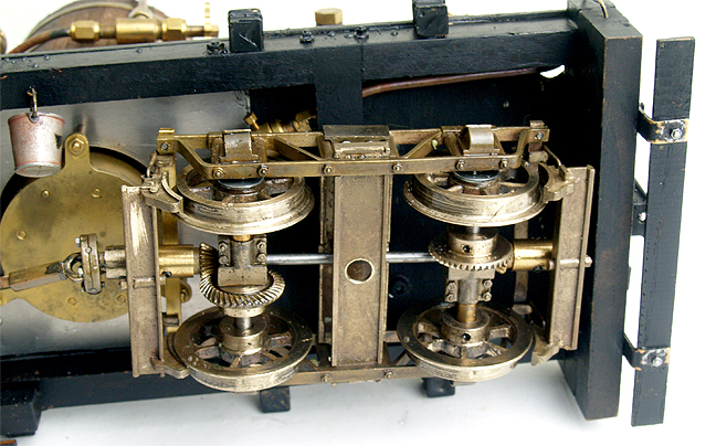
Also, in this photo the gas piping to the ceramic burner can be seen under the top (right hand) chassis rail, which, as per the original, is made of hardwood, as indeed is most of the engine. Metal has only been used next to the burner or where a lot of oil is to be expected.

Back to Sidestreet Bannerworks
Click here to find out how your engine can be featured!
This page and its contents
Copyright Sidestreet Bannerworks, 2013