
Back to Loco of the Month homepage
Back to Sidestreet Bannerworks
.
September 2008
Victor Harrison's Atlantic
by Marc Horovitz

Victor Harrison is a well-known name from the early days of gauge 1. His ultimate garden railway, the Hurst Railway, in Bishop's Stortford, achieved almost legendary status. It lasted for 20 years, finally being dismantled in 1953, six years before Mr. Harrison's death. Mr. Harrison was friends with other gauge-1 luminaries, including W.J. Bassett-Lowke, Henry Greenly, and J.N. Maskelyne, then editor of Model Engineer magazine. His railway and his work in gauge 1 appeared frequently in the British press.
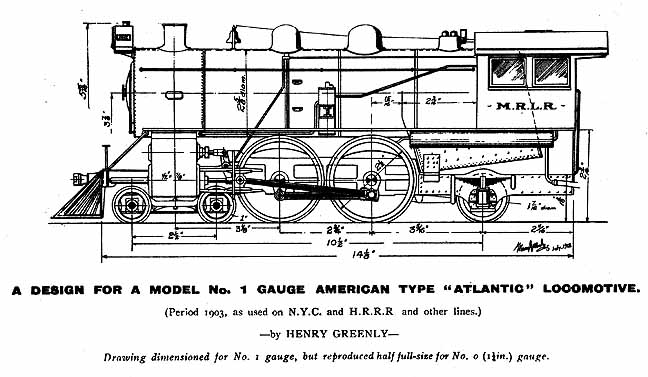
The Atlantic (4-4-2) wheel arrangement is not often modeled. These engines are often elegant and graceful, being primarly designed for passenger haulage. The locomotive in question was first described by Henry Greenly in the September 1912 edition of his magazine, Models, Railways and Locomotives. The engine caught the fancy of Victor Harrison, then around age 27. Mr. Harrison had an interest in American-style locomotives evidently kindled by a visit to the US. He undertook the construction of the engine that Greenly described (this would be his second US-style model), and a description of his model subsequently appeared in the April 1914 edition of Models, Railways and Locomotives, along with pictures of the model, both finished and under construction.
The model as built
This is a well made model that has seen lots of use. It seems large for 1:32 scale, perhaps because it was designed to the American loading gauge.To quote the builder. . .
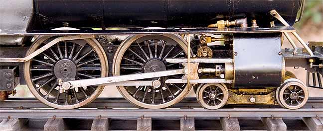
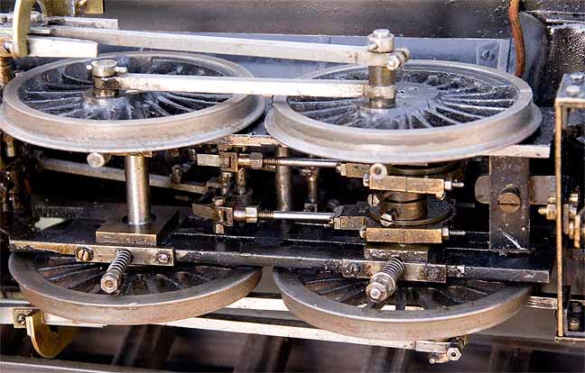
"The main frames were cut out of 1/8" mild steel and slotted out as suggested to represent American bar framing. Brass bearings are fitted to the four main axles. The leading bogie axles are fitted with equalizers and the trailing wheels are also mounted on springs.
"The cylinders were bought and are of the pattern suggested by the editor. The reversing is operated by the simple yet effective slip eccentrics. The connecting and coupling rods were filed up from the solid.
"The inner boiler is of solid drawn copper tube 1/16in. in thickness and the outer casing 1/32in. thick brass tubing with brazed joints. The ends of the inner boiler as well as the front of the smokebox are gun metal castings made from my own patterns. The conical front of the smokebox is removable for the purposes of getting up steam. Fittings in the cab consist of regulator, two test cocks, steam gauge, steam-blower valve, and check-valve which is connected to the water tank in the tender.
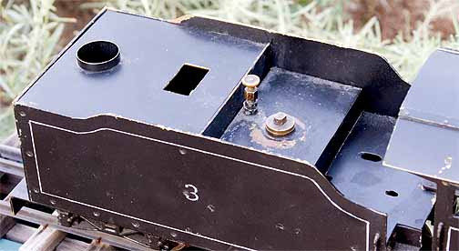
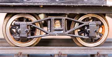
"The tender, which is built up from sheet brass, contains water and spirit tanks and also [an] "Ever-ready" battery for lighting the head light. In the water tank there is a small force pump, which is connected to the check valve. The tender bogies were purchased finished. The spirit tank is automatic drip feed which, once adjusted, I find is most reliable.
"The lamp [burner] itself has only three 3/8in. wicks and with careful adjustment are ample for maintaining 35 to 40 lbs. pressure which is all that is required.
"The safety valve blows off at 45 lbs. and does not let the pressure rise above 48 lbs, so is very convenient when the engine has to stand unattended.
"The two Westinghouse brake reservoirs underneasth the cab are used as displacement lubrication which supply more than sufficient oil."
Mr. Harrison goes on to describe the engine at work, hauling four wooden coaches in a driving rain storm.
The model today
The engine today is not in working order, though it might not take much to get it going. There appears to be a more-recently installed pump in the tender, along with a new sump for the fuel. The water line to the engine was badly soldered where it emerges from the tender and must be repaired.
The locomtive, also, has been modified. Perhaps the most significant change is that the original slip eccentrics are gone. They have been replaced by a simple-eccentric valve gear with reversing links, controlled by a lever in the cab. I don't know if this modification was done by Victor Harrison at a later date or by some unknown person. This gear, while apparently well made, does not seem to function properly at present.
I removed the smokebox front, which is held in place by an ingenious mechanism (see photos below). The smokebox is filled with gunk. The locomotive has obviously not been well cared for, as that amount of oily sludge would have taken a long time to build up.
When trying the engine under compressed air, applied to the boiler via the water line from the tender and the check valve, I could see that the pressure gauge (most likely not the original) works and the boiler seems steam tight. The blower also works, but when the throttle is opened, nothing at all happens, as if the steam line is blocked.
What this locomotive needs is a thorough stripping down and going through. There are a lot of small problems to be remedied, as well as a few larger ones. It will provide a good winter project some year, and I look forward to eventually having it back in steam.
|
|
|
| Builder | Victor Harrison (UK) |
| Date built | 1914 |
| Gauge | 45 mm |
| Scale | 1:32 |
| Boiler | Smithies |
| Fittings | Throttle, safety valve, check valve, pressure gauge, blower valve |
| Fuel | Alcohol |
| Blow-off pressure | 45 psi |
| Cylinders | Two, double-acting D-valve |
| Reversing gear | Simple eccentrics with reversing links |
| Lubricator | Displacement |
| Weight | Loco and tender: 14 pounds |
| Dimensions | Length (loco and tender), 25:; width, 4", height, 5-7/8" |


Below: Henry Greenly's drawing that appeared in 1912.
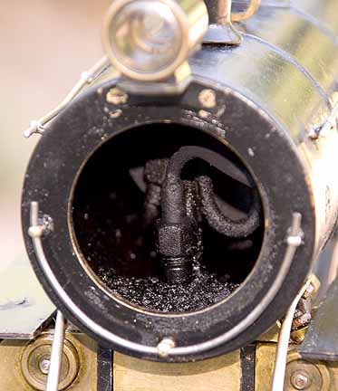
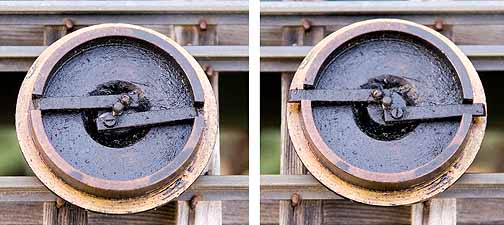
Above: The smokebox door is held in place by this ingenious latch mechanism. Turning the hex-bolt head on the front of the smokebox opens the latch.
In the lower left corner of the cab is the lubricator control valve. The lubricator has a separate line to the cylinders.
The coil in the center, below the footplate, is the water line from the tender. It is coiled to give it some flexibility, as the connection from the tender (which also has a coil of tubing) is rigid.
Below: The three-wick burner.

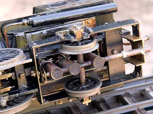
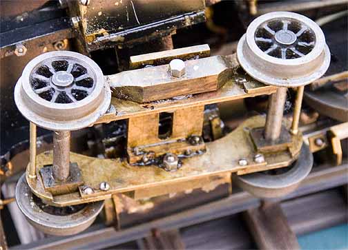


Below: A tender truck -- one of the few commercial parts the builder purchased.
Back to Loco of the Month home page
Back to Sidestreet Bannerworks home page
This page and its contents
Copyright Sidestreet Bannerworks, 2008
.