Back to Sidestreet Bannerworks
June 2001
15" 0-4-0T for gauge 1
by Marc Horovitz

Ever since I was I child, I've been interested in railways of the smaller variety. I used to take the bus to the main library in downtown Denver to check out Frederic Shaw's Little Railways of the World. It was here that I learned about 15"-gauge. I was especially interested in the British lines—the Romney, Hythe & Dymchurch and the Ravenglass and Eskdale. I later learned about Sir Arthur Heywood, who proposed the notion that 15" gauge was the smallest practical gauge for a full size, narrow-gauge railway. Sadly, he built only two lines to this gauge; his own, experimental Duffield Bank Railway and, later on, the Eaton Hall Railway for the Duke of Westminster. He called these "minimum-gauge" railways and wrote a fascinating treatise on the subject.
For me, as well as many others, 15" became a sort of magical gauge. I never really considered modeling 15"-gauge equipment until I met Mike Decker many years ago. Mike is a strong proponent of this gauge and is an authority on Sir Arthur Heywood’s railways. Mike began producing castings for 1-1/2"-scale models of 15"-gauge equipment to run on gauge-1 track. (Gauge one actually works out closer to 14.2", but this is close enough for most modelers.) I purchased some wheelsets from Mike, along with some pedestals and couplers, and began building my own 15"-gauge equipment in gauge 1.
Alas, though, I had no locomotive. I had neither the time nor the inclination to build a scale model of any of Heywood's locomotives, attractive thought they might be. I had in mind a freelance engine, something with relatively simple valve gear and a pot boiler that wouldn't take a long time to build.
Enter an old friend, Mike Bigger, of Narrow Gauge Machining (ngmikeb@aol.com). I discussed the idea with him and we agreed that if I designed the engine and provided him with a complete set of drawings, that he would build a small batch of them. The locomotive that is the subject of this review is the first of that batch, what might be considered the pilot model. It is a wonderfully made locomotive.
The engine
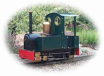
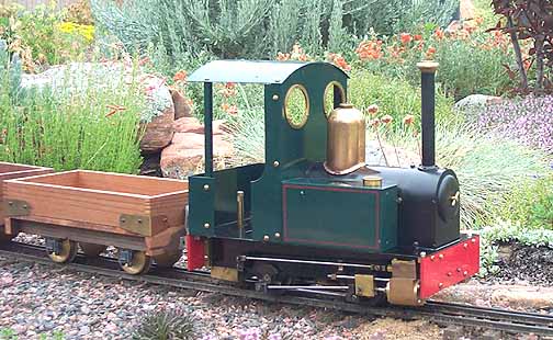
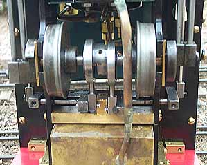
A simple pot boiler, fired by a four-wick alcohol burner, supplies the steam. The backhead is fitted with a standard needle-valve throttle, a pressure gauge, and a blowdown valve. The cylinders are controlled by D-valves. Reversing is via slip eccentrics. The eccentrics are on the rear axle and drive rocker arms to the rear. A mammoth, polished-brass dome sits astride the boiler, as is only right. A firebox, based on Jack Wheldon's principles, resides inside the dummy side tanks. Blow-off pressure is around 50 psi. Drivers are solid disks and are made to the same profile as the wheel Mike Decker provides. No castings are employed in this locomotive.
The locomotive stands a scale 6' tall, or nine real inches, making it half again taller than, say, a G-scale engine. Its proportions are decidedly different—sort of squat and chunky—giving the engine and its train a unique character. Unfortunately, I don't have any figures in 1.5" to really give the engine scale.
Performance
Operating this locomotive is very straightforward. After it is oiled all round and the lubricator and meths tank are filled, the blowdown valve is opened and the boiler filled with water until it begins to drain out the blowdown pipe. Then the fire is lit and we sit back for a few minutes. After a little while, steam begins to spurt from the blowdown pipe and the valve is closed. Pressure comes up quickly after that.
Once the clock shows pressure nearing blow-off, the throttle can be opened. Surprisingly, this engine doesn't take much coaxing. Just a little push to warm the cylinders and it's away.
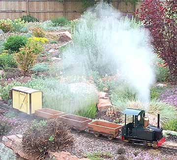
On this day it had a light load of three empty wagons (based on Heywood's standard design) and a freelance boxcar. The engine pulled this train easily and sedately around my loop, pausing every ten minutes or so to have the fuel topped up. The run lasted maybe 45 minutes or so—I really didn't time it. Sometimes the train would slow to a stop, but would then start up again on its own after half a minute or so, the cylinders still warm. It was a cool, damp day in Colorado, and the steam effects were all anyone could wish for. With its chunky proportions and surrounded by clouds of steam, it brought to mind a different era of railroading.
| Specifications | |
| Builder | Mike Bigger |
| Designer | Marc Horovitz |
| Date built | 1994 |
| Gauge | 45mm (gauge 1) |
| Scale | 1.5" = 1'-0" |
| Boiler | Pot boiler |
| Fittings | Safety valve, throttle, pressure gauge, blowdown valve |
| Fuel | Alcohol |
| Blow-off pressure | 50 psi |
| Cylinders | Two, double acting D-valve |
| Reversing gear | Slip eccentric |
| Lubricator | Displacement, in the cab |
| Dimensions | 10-1/4" long x 5" wide x 9-1/8" tall |

Above right: The underside. The burner is a standard alcohol type. The wick tubes are protected on the bottom by a plate, making the engine a little difficult to light.
Right: The left side of the loco. The lubricator stands in the cab door. It is drained by removing the screw at the bottom.


Back to Sidestreet Bannerworks
This page and its contents Copyright Sidestreet Bannerworks, 2001