
Back to Sidestreet Bannerworks
February 2002
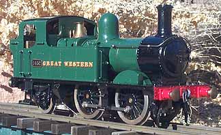
Brandbright GWR 0-4-2T
by Marc Horovitz
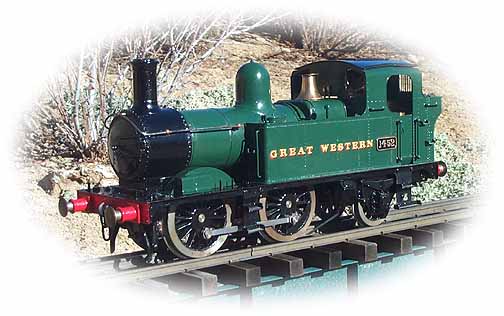
The Great Western Railway developed its 14XX-class 0-4-2T for rural branchline service. The engine was designed by C.B. Collett. Despite its slightly old-fashion appearance, the 14XX was, in fact, a relatively modern locomotive, being first brought into service in 1932. In all, 75 were built.
These engines were used on branch lines all over the GWR system, usually in push-pull service, often with just a single coach. There was a compartment at the far end of the coach from which the driver would control the engine, through both direct linkages and a system of signals to the fireman, on the return trip. Since these trains often provided the best link to the outside world, they were looked upon with some affection by the local residents, who usually bestowed nicknames on them. For instance, the train from Maidenhead (on the mainline) to Marlow was known as the "Marlow Donkey."
Many of this class of engine lasted until nearly the last days of steam in Britain. The remaining ones were officially withdrawn from service in 1965.
The model
In 1990, Brandbright Ltd. produced an interesting model of this small engine. In outline, it well captures the character of the prototype. The level of detail is good and the platework, assembled from brass etchings made from artwork by Donald Pearse, is festooned with rivets. It is nicely painted and crisply lettered.
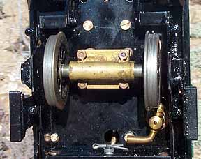
Mechanically, this is an odd duck. It is powered by a four cylinder, oscillating steam motor. The motor, developed by Peter McCabe, was made by Ian Pearse. It has two small cylinders on either side that work in tandem, each pair driving a yoke that engages the crankpin. A small gear on the crank axle drives a larger one on the driven axle. The engine's frames are actually only cosmetic, as the axles are supported by a central frame that is integral with the steam motor. Reversing and speed regulation are via the sort of rotary valve customarily associated with oscillating engines and is controlled from the cab by a single lever. The trailing axle is sprung and has considerable lateral play for negotiating tight curves.
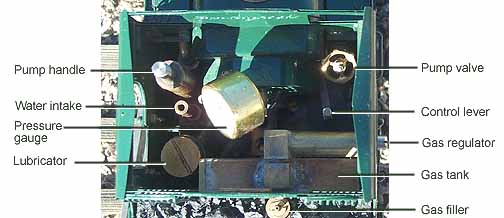
The cab itself is cramped. On the left side is a small hand pump. You are supposed to fit a rubber tube over the inlet and pump the boiler up that way. However, there is no water glass, so you'd have to run the boiler dry each time to know how much water to put back in. A valve on the right side of the cab opens and closes the line from the pump. A displacement lubricator sits right behind the left-hand door. It has a drain conveniently hidden (or inconveniently placed, depending on your point of view) behind the step.
A gas tank resides in the bunker, with an unobtrusive filler valve in the coal pile, just behind the cab. The control-valve stem protrudes from the right-hand door and must be operated with a screw driver, as no handle is provided. The boiler itself is a traditional, center-flue boiler.
As mentioned above, control is via a single lever in the cab, accessible through the removable roof. This is difficult to reach, especially when the engine is hot, and it tends to flop around. Although offered in a manual version, the locomotive was intended for single-servo radio control, which obviated the control problem.
In all, only about a dozen of these models were produced.
Performance
The run day was a fine day in February, with clear skies and the temperature around 50 degrees. After lubricating all around, I filled the boiler with distilled water. As mentioned above, using the pump is a little problematic, so I opted to fill through the safety valve, which resides beneath an attractive, removable cover. The valve housing itself has no knurls or flats to grip, so getting it off the first time was difficult. The first thing I did was file some flats on it so it could be removed in the future with an adjustable wrench.
Steam is taken from the boiler through a pipe in the steam dome. I filled the boiler around three-quarters of the way up. The safety valve was replaced and the gas tank filled in the usual way. The lubricator was drained through its valve and refilled with steam oil. The gas valve was cracked with a screwdriver and the burner lit immediately from the stack.
After a few minutes, steam was up to 40psi. Because of the difficulty in reaching the control lever, I slipped a brass tube over it that extended through the cab roof. This made setting the throttle much easier. Once the engine was running at a good speed, I removed the tube and replaced the roof. The engine ran steadily, with an audible exhaust beat.
The run lasted just over 10 minutes, when the boiler ran dry. I quickly shut off the gas and allowed the engine to cool. Since there is no throttle valve between the lubricator and the boiler, oil tends to be sucked back into the boiler as the engine cools. So far, this has not affected performance.
Despite its difficulties, I like this engine. It is a runner's engine, not an operator's engine, at least in its manual incarnation. Because of the difficulty in reaching the control lever, the loco can't be easily stopped and/or reversed without removing the roof and re-engaging the cheater tube over the control lever. However, once it's running, it is hard to find fault with it. It looks just right traversing the miniature countryside. Now I need to find a suitable coach for it.
|
|
|
| Builder | Brandbright Ltd., England |
| Date built | 1990 |
| Gauge | 45mm (gauge 1) |
| Scale | 1:32 |
| Boiler | Single flue, internally fired |
| Fittings | Throttle/reverse lever, hand pump, feed-line valve, pressure gauge, safety valve |
| Fuel | Butane gas |
| Blow-off pressure | 45 psi |
| Cylinders | Four, double-acting oscillators, working two and two |
| Reversing gear | Rotary valve controlled from cab |
| Lubricator | Displacement |
| Dimensions | Length over end beams, 10-1/4"; width, 3-3/8"; height over stack, 5-1/8" |
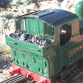
Right: The back of the cab. Note the fine grill over the cab windows and other detail.
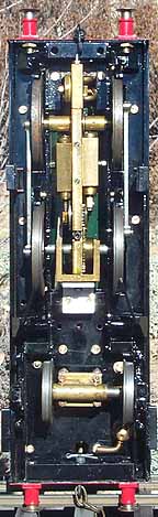

Left: The underside of the engine. Here you can see the central frame that supports both the axles and the steam motor. The reversing valve is at the top of this frame and steam passages are carried within it.
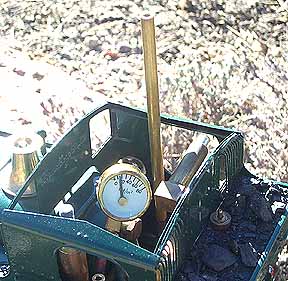
Right: Pressure is beginning to show on the gauge, The brass tube has been slipped over the speed/direction lever for better control. It is removed when the engine is under way.
Back to Sidestreet Bannerworks
This page and its contents Copyright Sidestreet Bannerworks, 2002