
Back to Loco of the Month homepage
Back to Sidestreet Bannerworks
.
April 2007
Aster's C&S Mogul
by Marc Horovitz
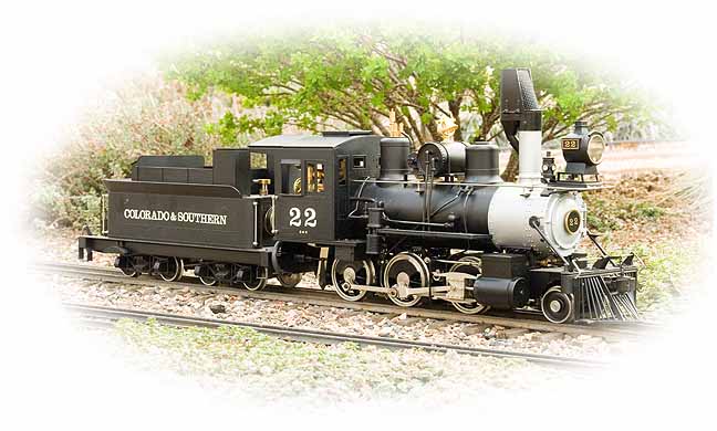
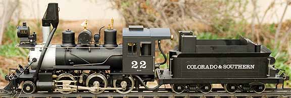
Colorado & Southern's No. 22 was one of a batch of 16 identical Moguls purchased by the Union Pacific Railroad from Brooks in the early 1880s for its then Denver, South Park & Pacific Railroad in Colorado. In 1902, after some typical haggling and wangling, the 3'-gauge railroad became independent with a new name, the Colorado & Southern. The C&S was later acquired by the Burlington Railroad, but retained its name until the end. By the time the C&S came into existence, only two of the original 16 Brooks engines remained: Nos. 21 and 22. By this time both had been extensively rebuilt, probably ending up with a fair amount of parts from similar Cooke engines on them. Aster's model represents the locomotive toward the end of its life in the mid 1920s. It was scrapped in 1927. (Thanks to Aster for this information.)
The engine
This model is a butane burner. The gas system has a couple of unusual features. The first of these is a sight glass (actually a little window) in the generous fuel tank. The gas (which is stored in its liquid state) is clearly visible, giving the operator an indication of how much is left. The other unusual feature is a secondary tank in the cab, between the storage tank and the burner, which is also equipped with a control valve. This was evidently intended as a sort of buffer to even out the gas flow and make the burner more controllable. It turned out to be problematic and many owners removed it entirely, piping the gas directly to the burner in the usual way. The boiler is a conventional single-flue type.
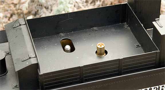
The backhead has the usual fittings, including a throttle (controlled by a wheel instead of a lever), a pressure gauge, a water glass, and an awkwardly placed blowdown valve beneath the boiler under the cab. There are two safety valves, one under the steam dome and one inside the cab. The latter vents through the cab roof via a silicone tube. The tender is fitted with a hand pump to keep the boiler topped up. The gas tank sits in the water reservoir to help keep the gas temperature constant, especially on colder days.
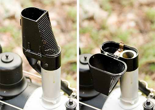
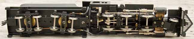
Cylinders are the typical double acting, slide-valve type. Reversing is accomplished by a single, simple eccentric for each valve, connected to an expansion link so that reversing can be controlled from the cab. (The prototype had Stephenson's link motion.) Motion is brought through the frames via rocker arms. A dead-leg lubricator resides on the pilot deck, in front of the smokebox. The model features the prototype's distinctive "bear trap" spark arrestor and the interesting air tank atop the boiler. Cab controls are accessed by removing the rear section of the cab roof.
The run
Run day was moderate and sunny. I prepared the engine in the usual way, oiling it and topping up all its fluids. When all was ready, I set it on the track and folded down the top part of the spark arrestor for lighting up. I cracked open the gas valve and opened the secondary valve a little. Here's where trouble began. Both of the gas valves are extremely sensitive. Most of the control comes within a degree or two of motion and it is very difficult to control the gas flow.
After several false starts I finally got the fire lit. With the gas set properly, the fire flashes back with no problem. However, once lit, there was still an ongoing problem with surging and the fire had to be relit two or three times. When the gas level dropped some, this problem abated and all was good.
When the pressure came up, I opened the throttle and the engine moved smoothly off, with no cylinder condensation. This is an extremely smooth-running locomotive. Also, it has about the loudest exhaust beat I've ever heard in an engine of this size. Just why this is, I don't know. Possibly something to do with the smokebox acoustics. In any event, it could be easily heard at any point on the railway and the noise alone was effective in letting me know just where the engine was when it was out of sight.
The run lasted perhaps half an hour, with one or two stops for pumping water. The gas tank is large, so the water level must be diligently attended. The throttle valve, like the gas valves, is sensitive, and getting the engine to run light at a reasonable speed was a little tricky. However, we soon came to an agreement and the run proceeded in a most satisfactory manner.
|
|
|
| Builder | Aster (Japan) |
| Date built | 1991 |
| Gauge | 1 (45 mm) |
| Scale | 1:22.5 |
| Boiler | Single flue |
| Fittings | Safety valves (2), throttle, water glass, pressure gauge |
| Fuel | Butane |
| Blow-off pressure | 60 psi |
| Cylinders | Two, double-acting D-valve |
| Reversing gear | Simple eccentrics with reversing links |
| Lubricator | Displacement |
| Weight | 14 pounds, 6 ounces (loco and tender) |
| Dimensions | Length over all, 24-3/4"; width, 4"; height over stack, 7-3/4" |


Above right: The displacement lubricator is located on the pilot deck.
Right: The cab is pretty crowded. The wheel is the throttle. On the left side of the cab is the auxiliary gas tank with its attendant valve. The thing that looks like an eyelet in the cab roof is the exhaust vent for the safety valve that's in the cab. The reversing lever can just be made out on the right side.


Back to Loco of the Month home page
Back to Sidestreet Bannerworks home page
This page and its contents
Copyright Sidestreet Bannerworks, 2006
.