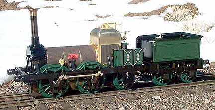
Aster’s new Lion kit
Construction notes and photos
by Marc Horovitz
Here, I’ve gone through the instructions section by section and included a photo of each completed subassembly, for whatever good these may provide. They are in black and white to reduce download time.
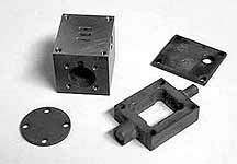
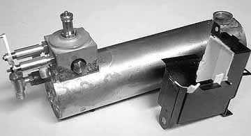
Right: The blackened cylinder parts.
Step 8. You are instructed to install a 2.4 nut. This should read 2.0 nut.
Step 11. Before screwing the 1-15 guide tube over the 1-14 piston gland, make sure the piston rod is pulled all the way out. This will make things easier later.
Step 2. Before I could install the bushes into the frame, I had to lightly file the paint off the inner edges of the recesses for a smooth fit.
Step 7. The front end of the connecting rod fouled the tube and had to be filed a little to clear.
Setting the valve on this engine is dead easy.
Section 4: Boiler assembly
Step 2. It is mentioned at the end of this section that holes in the valve handles might need filing. I found this to be so and used a variety of needle files to open out the oblong holes.
Step 5. Adhering ceramic sheet D was a little baffling, but the drawing in section 8 helped to clarify it.
Step 3. Adhering 4-9 pattern G is the most incomprehensible part of the whole instructions, to my mind. I still don’t know what was intended, but here’s what I did. I glued the sheet to the inside of the smokebox with the silicone provided. Then I very carefully cut out the rectangle that covered the smokebox-door opening with an X-acto knife. I then screwed the smokebox door in place and, from the inside, took the little rectangle I had just cut out and adhered it to the inside of the smokebox door. When the silicone had hardened, I removed the smokebox door, with the ceramic adhered to it perfectly in position.
After the smokebox had been mounted to the boiler, I then cut the ceramic sheet along the bottom of the smokebox. I cut in from either side, toward the center, but not all the way. I then folded the exposed bottom section under the boiler, covering the hole in the bottom of the boiler shell, and glued it securely in place with silicone. This may or may not have been what was intended, but it worked.
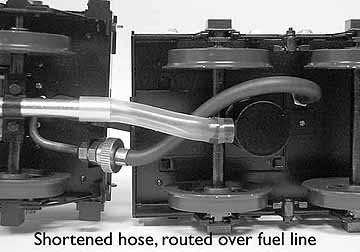
Step 5. To properly install the blower pipe, it must be bent to fit in its proper position. Also, when securing the pipe to the blower valve, insert the pipe into the valve as far as it will go, then tighten the fitting. This is a compression fitting and the first time the nut is tightened, the little union is deformed into the pipe itself, making a steam-tight connection. If the blower pipe is not inserted far enough, you’ll compress the union around air, not achieving the desired effect and ruining the union.

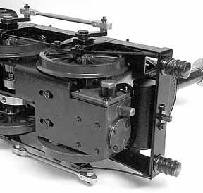
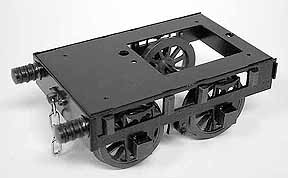
Step 2. I had to file the frame edges slightly to get the axle boxes to smoothly slide on. This is not so important with the front, unsprung axle, but the rear driving axle is sprung and the axleboxes should move smoothly in the frames.
Step 6. In mounting the steps, I found the bolt holes just a little small and had to open them out a little with a tiny rat-tail file.
Step 1. When screwing on the lubricator cap the first time, I found it to be a very stiff go. This might have been due to paint in the threads. After the first time, all was OK.
Step 5. The instructions say to insert the rear ends of the wires into the side of the end beam. They are actually to go into the holes provided in the steps, as per the drawings. It would have been nice if Aster had provided a pattern for bending in the instructions. A little trial-and-error may be necessary for a good fit.
Section 8: Mounting the boiler
Step 7. Do this step before securely fastening the firebox in place.
Step 9. This is the step they left out. Fasten the firebox to the footplate with 2x4 BS screws.
Step 1. The front end of the front splashers hold the smokebox in place. This wasn’t clear in the instructions.
Step 3a. (Another omission.) Attach the backhead to the footplate with 2x4 hex screws.

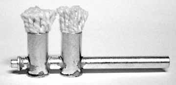
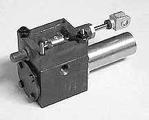
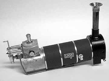
Above right: The burner.
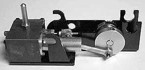
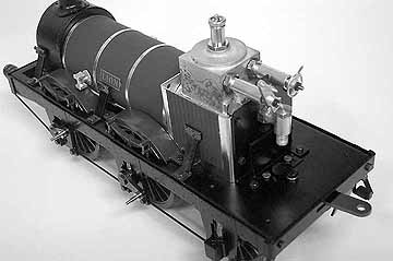
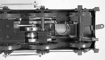
Right: Underneath the rear of the engine. The burner has not yet been installed in the firebox.
Air test. Having tested the steam motor previously, this second air test was routine, the engine turning over smoothly in both directions.

Step 3. The last two sentences are misplaced and extraneous. Disregard.
Section 13. Tender water and fuel tank
I ran out of wire for steps 1 and 2. Again, bending patterns would have been most welcome. I happened to have some of the same wire left over from another Aster kit, so was saved.
Section 14: Coupling the engine and tender

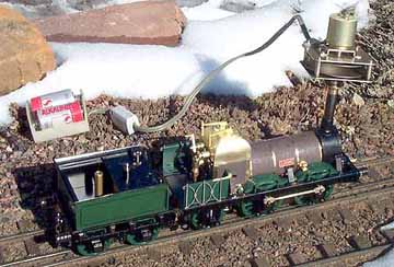
I was pleased with the performance of the engine. It is, however, a touchy beast. The balance between go and no-go seems quite delicate and it will take a practiced hand to get the best operation out of it.
Performance straight from the construction bench was very good indeed. The engine runs very smoothly. Don’t expect success, though, if there isn’t enough pressure. At blowoff pressure, or near, you’ll have enough steam to operate the blower (hence maintaining pressure) as well as running the engine. If you run at speed, the exhaust should maintain the fire and you can shut off the blower. When running more slowly, you might want to leave the blower cracked a little.
[Note: Andrew Pullen is the UK importer for Aster and was involved with Aster's model during its development. He has more experience with this engine than probably anyone else at this time. Conact him at info@asterhobbies.co.uk —MH]
1. The fancy ironwork around the cab side sheets should be black as well as the “crown” of the “Haycock” firebox.
2. Red paint is not provided with the Thunderbolt kit, although the instructions say otherwise. I am having some paint mixed to match in the UK and will provide detailed painting notes for anyone wanting to get this right. Geoff Calver has some stills of the film that show the essentials well enough. I'm sure Geoff would make these available to anyone interested. Contact him at geoff.calver@dial.pipex.com
The blank plug on the boiler is for a pressure gauge and I will market a kit of parts to adapt this for use using a sub-miniature gauge, which I also sell. This should help the less experienced.
The trick with running the Lion is to listen to what is happening and always have a syringe of water handy! With experience you can hear when you have injected enough water for the blower to “pull up” the fire before giving it some more water. When the blower “spits,” stop adding water, and when the noise level comes up to just before “blow off,” open the regulator. I have had a pre-production sample for over a year that pulls four bogie coaches. I can give it a shot of water every seven minutes and have a virtually non-stop run.
Finally the wick material supplied by Aster is poor and not what I advised. This is why you are needing to crack the blower on etc etc. With hindsight, a three-wick-tube burner would have been better and one tube could have been capped if the fire got to be too much. I use mineral wool, which gives more fire and means a quick recovery after adding water and no need for blower to be on when running. This material is called “Kaowool” in the UK. It is rather like cotton wool in texture. Carefully packed into the wick tubes, it is as good as asbestos. The insulation used by Aster is the more solid “card” version of the same material.
Back to Sidestreet Bannerworks
This page and its contents copyright 2001 by Sidestreet Bannerworks