
Back to Sidestreet Bannerworks
November 2001
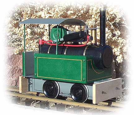
Denver 0-4-0T
by Marc Horovitz
A year or so ago, members of the Denver Steam Group decided that we would like to have a project locomotive to build. We didn't want an engine that could be assembled from ready-made components, as that was already available in the form of the project engine designed by members of the Bay Area Garden Railway Society. We wanted a locomotive that would be largely scratchbuilt, with just a few purchased components. The object of this exercise would be to raise the general level of metalworking capabilities of club members.
After much discussion, it was decided that the engine would need to be buildable with only a small lathe (Taig, Sherline, Unimat, etc.) and drill press as the main power tools. Its design would need to be as simple as possible, but (ideally) something interesting and something that would lend itself to modification by the builder, if so desired. It had to be made with common, readily available tools and materials -- nothing exotic or out of the way.
A design committee was formed, consisting of Jim Reyer, Ken Orme, Bruce Holmes, and myself. With the above mandate firmly in our grasp, we set off.
The result
After what we felt were far too many months, we arrived at a design that pleased us all. It is an overtype engine (the steam-engine part is on top) with a simple pot boiler made out of a bit of standard plumbing. The engine drives a primary shaft with a pinion gear on it, which drives a larger gear on a secondary shaft, providing an initial gear reduction. The secondary shaft has a small ladder-chain sprocket at one end. The chain powers a larger sprocket on the locomotive's rear axle, providing a second reduction. The overall reduction is around 6:1. The two axles are linked with additional chain and sprockets inside the frame.
The frame is made of a piece of 1-1/2"-square aluminum tubing with one side cut off to form a U-shaped channel. Axles are made from stock rod and the wheels are purchased from Sierra Valley Enterprises. The holes in the wheels are larger than the axles, so have to be bushed down. The frames are slotted for the axles, which go in from the bottom and are held in place by retainer bars.
The boiler is made from a piece of 1-5/8" OD copper tubing. Two standoffs on the bottom are used to attach it to the aluminum frame. Two bushings on the top are used as motor mounts. Also on top of the boiler are a stud over which the smokestack fits, a safety-valve bushing, and a steam takeoff bushing.
The engine is alcohol fired by a traditional three-wick burner. The fuel tank resides beneath the cab. Alcohol was chosen because of the simplicity of the system as well as the relative ease of burner construction.
Dummy side tanks are easily folded up from sheet brass. These serve as the firebox and are insulated with Fiberfrax, a refractory material, which helps to hold some of the heat in. The tanks are not physically attached to anything, but are trapped in place when the boiler is installed.
The lubricator is a standard displacement lubricator, made from tubing and the like, and it is hung off the steam line aft of the boiler. The entire lubricator body unscrews from the steam line, facilitating emptying and filling. The safety valve is a purchased product. Plumbing is K&S copper tubing.
The frame of the steam motor itself is a piece of 1"-square steel tubing, again with one side cut off to form a channel. The three of us who built engines each came up with a different design. (Two of the different designs are presented in the plans.) Ken and I used one single-acting oscillating cylinder, while Jim designed a more complex double-acting engine. All of the engines work well. In each, steam is exhausted to the stack, which is simply another piece of K&S tubing.
The locomotive is finished off with a rudimentary plantation-style cab. This is made of two brass rods and two pieces of sheet metal. It comes right off for access to the backhead.
Performance
Running any of our three engines is no different from running any simple engine. Oil all around, fill the boiler with distilled water, the lubricator with steam oil, the alcohol tank with meths, and light up. After six or seven minutes, with the safety valve sputtering, you grab the buffer beams and give a push, making sure the wheels are turning. Once the condensate has cleared, off it goes.
We each used a different wick material. Ken used fiberglass yarn, Jim used stainless-steel screen, and I used asbestos. The consensus is that asbestos works best.
Two of the engines (Jim's and Ken's) run quite smoothly, while mine vibrates some. I'm still trying to sort out the reason why. It may be the imbalance in the piston rod / flywheel, or it may be back pressure in the exhaust system. However, this is a minor problem and the engine runs just fine.
Disadvantages and advantages
Because of its simplicity, this locomotive has limitations. As designed, it is not reversible and it has no throttle -- it just goes. Also, it gets HOT (but no hotter than a lot of other pot boilers I've seen). Wooden end beams are a necessity for lifting the engine and getting it going. If alcohol gets spilled and ignites, the end beams can suffer.
On the plus side, this engine is about as easy to build as any we have seen, which is not to say that it's necessarily easy to build. If you have no machining or metalworking experience, you've got a fairly steep learning curve to get up to speed, but this engine was designed to help you get there. Nobody was born with machine-shop skills -- everybody had to learn sometime.
There are only about three truly critical dimensions in the entire engine. These include the fit between the piston and the cylinder; the distance between the pivot point of the cylinder and the centerline of the primary geared shaft; and the distance between the primary and secondary geared shafts (so the gears mesh properly). If you are off a little in any of the other dimensions in the whole engine, it shouldn't affect performance too much.
Since the steam motor is designed as a separate unit, virtually any engine can be made and strapped onto the boiler, as long as it will drive a chain down to the wheels. That's how we got away with coming up with three different engine designs. (In fact, Jim had a fourth design for a single acting, fixed-cylinder engine).
The engine's boiler is big enough to allow a reasonably long duration (20 minutes or more, if all is well), with a couple toppings up of the fuel tank. It is powerful enough to haul half a dozen lightweight cars on a level track.
| Specifications | |
| Designers / builders | Jim Reyer, Ken Orme, Marc Horovitz |
| Date built | 2001 |
| Gauge | 45mm (gauge 1) |
| Scale | 1:20.3 (nominal) |
| Boiler | Pot |
| Fittings | Safety valve |
| Fuel | Alcohol |
| Blow-off pressure | 40 psi |
| Cylinders | One single-acting oscillator (as designed) |
| Reversing gear | None |
| Lubricator | Displacement |
| Dimensions | Length over end beams, 6-5/8"; width, 3-3/8"; height over stack, 6-1/8" |

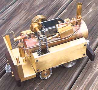
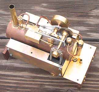
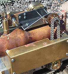
Above right: Jim Reyer's engine features a double-acting oscillator. He also fitted a throttle to the banjo fitting at the back of the boiler, from which the steam line emerges. His engine's chain is on the right side of the boiler, while the other two are on the left.
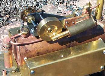
Center right: The cylinder shown here on Ken Orme's engine is a fixed, single-acting unit with a rotary valve that didn't work out well. Ken replaced it with a single-acting oscillator. The cylinder is on the left side, the flywheel is on the right, and the chain is on the left. Ken also used a cut-down 1" aluminum tube as the frame for his steam motor.
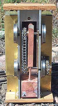
Below right: Marc Horovitz's engine also has a single-acting oscillator. However, in this engine, the cylinder and flywheel are both on the right, while the chain is on the left.
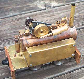
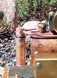
Right: The lubricator hangs in space from the steam line at the rear of the boiler. The lubricator body is unscrewed from the cap, which is tied into the steam line. This makes servicing easy.
Our Sources & Resources page will tell you where you can buy plans for the engine, as well as materials needed to build it. There are links there to tool suppliers, a Gallery of Denvers built by others, and a Question & Answer page.
Back to Sidestreet Bannerworks
This page and its contents Copyright Sidestreet Bannerworks, 2001